Grooved Water Connections: Refer to mechanical Data Tables
Evaporator Water Drain/Bleed: 1/2”
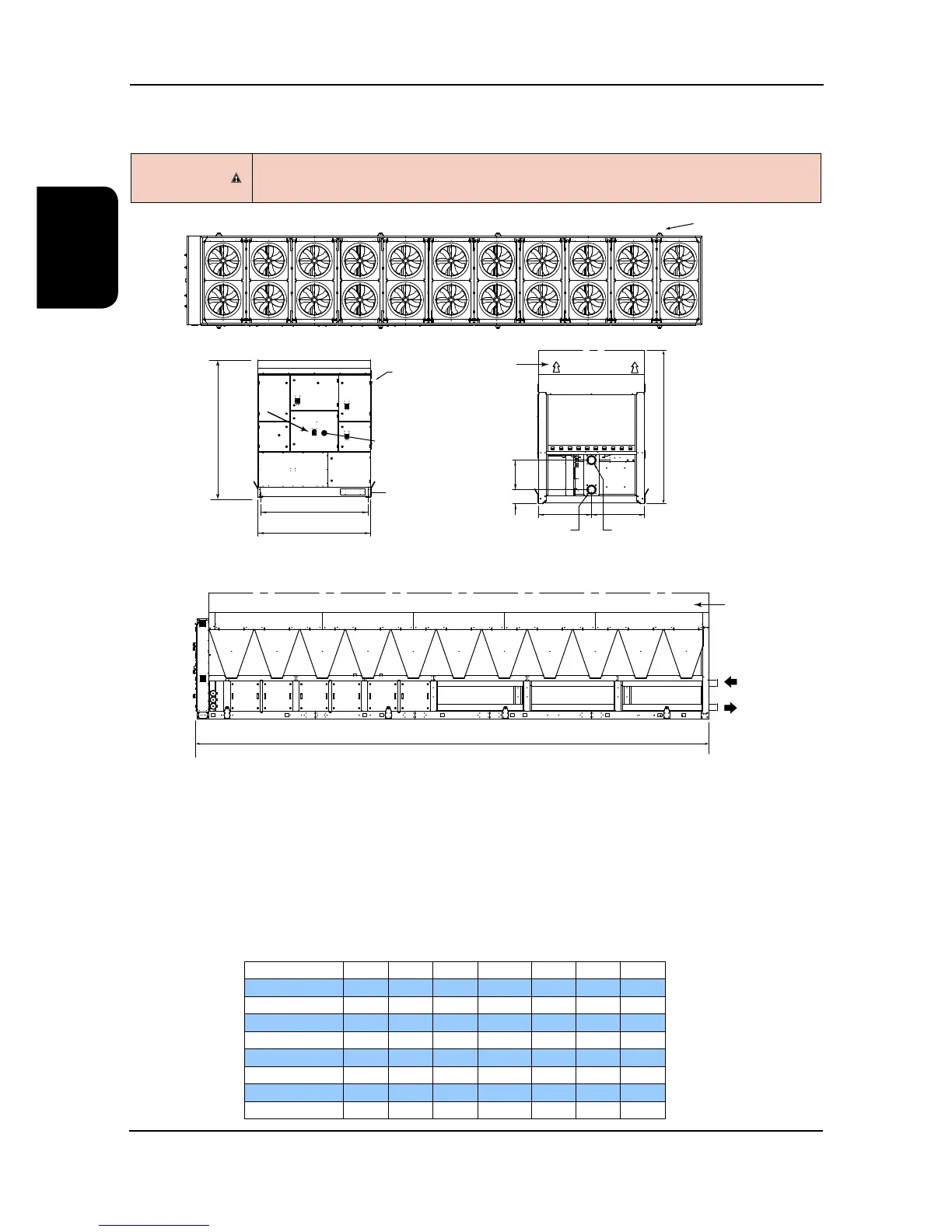
A B C D E F
8 Fan Case mm 2682 2200 4846 550 206 3182
10 Fan Case mm 2682 2200 5978 550 206 3182
12 Fan Case mm 2682 2200 7110 550 206 3182
14 Fan Case mm 2682 2200 8242 550 206 3182
16 Fan Case mm 2682 2200 9374 550 206 3182
18 Fan Case mm 2682 2200 10506 550 206 3182
20 Fan Case mm 2682 2200 11638 550 206 3182
22 Fan Case mm 2682 2200 12770 550 206 3182
(1) Mains Electric Isolator(s).
(2) Electric Control Panel - Circuit 1 and Circuit 2 and Circuit 3.
(3) Microprocessor Control Panel.
(4) Bus Bar Chamber / Incoming Customer Mains supply.
(5) Emergency Stop.
(6) Mains Cable Entry and route to Busbar, unit incoming mains isolation supplied by others.
(7) Water Connections: Water Inlet
(8) Water Connections Water Outlet.
(9) Optional discharge plenum extension
(10) Lifting Eye Bolts (removable).
Installation Data
Dimensions
(9)