Installation Data
Water Systems and Recommended Flow Schemes
Component Recommended Requirements
The recommended requirements to allow commissioning to be carried out correctly are:
● The inclusion of Binder Points adjacent to the ow and return connections, to allow temperature and pressure
readings.
● A ow switch or equivalent, tted adjacent to the water outlet side of the Chiller.
● A 20 mesh strainer tted prior to the evaporator inlet.
● A water-ow commissioning valve set tted to the system.
● In multiple Chiller installations, 1 commissioning valve set is required per chiller.
● Air vents are to be installed at all high points and where air is likely to be trapped at intermediate points.
● Drain points are to be installed at all low points in the system and in particular adjacent to the unit for maintenance
to be carried out.
● Isolating valves should be installed adjacent to all major items of equipment for ease of maintenance.
● Balancing valves can be installed if required to aid correct system balancing.
● All chilled water pipe work must be insulated and vapour sealed to avoid condensation.
● If several units are installed in parallel adjacent to each other, reverse return should be applied to avoid
unnecessary balancing valves.
Pump Statement
When installing circulating water pumps or equipment containing them, the following rules should be applied:
● Ensure the system is lled with water then vented and the pump primed with water before running the pump, this is
required because the pumped liquid cools the pump bearings and mechanical seal faces.
● To avoid cavitation the NPSH (Net Positive Suction Head) incorporating a safety margin of 0.5m head must be
available at the pump inlet during operation.
Interlocks & Protection
Always electrically interlock the operation of the chiller with the pump controls and water ow switch.
These safety devices prevent the chiller operating with low water ow which can cause serious damage.
Failure to install both safety devices will invalidate the chiller warranty.
2
1
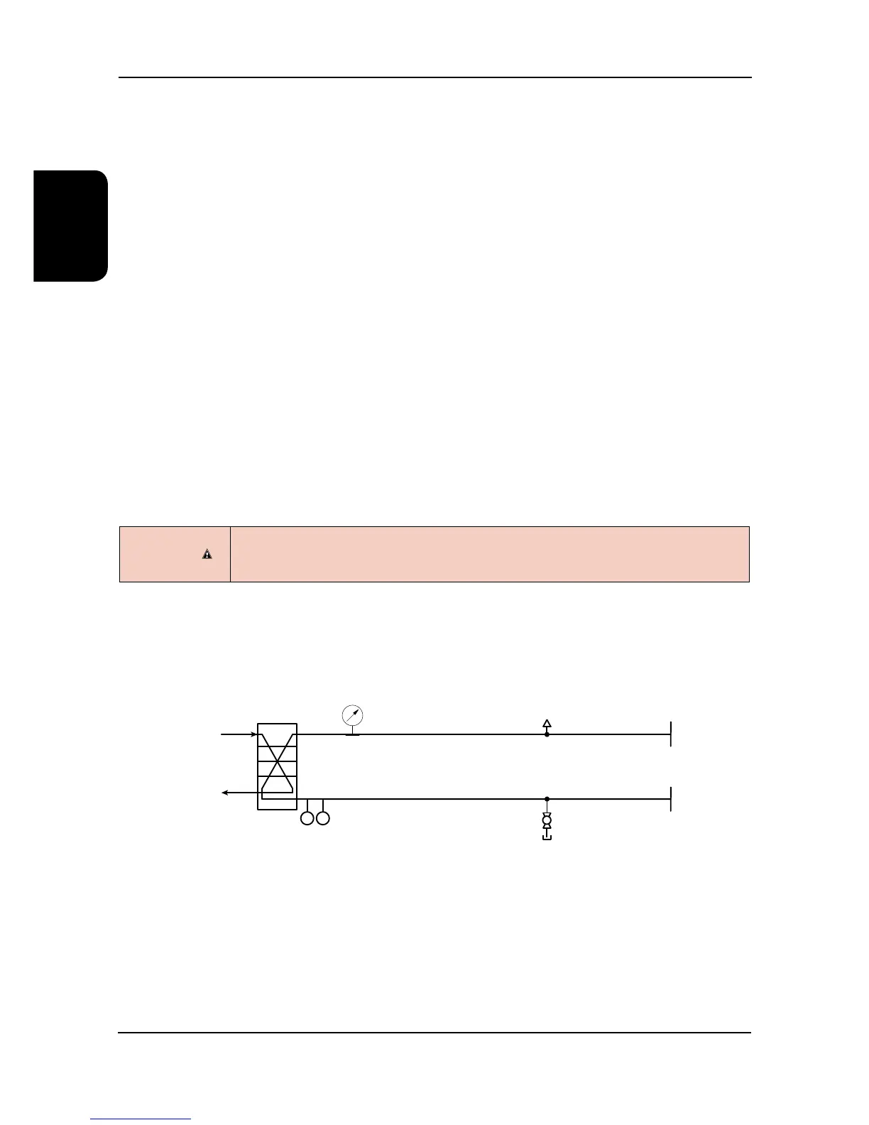
Flow Schemes
1 Water In 2 Water Out
Basic Supplied Water Schematic
(Includes Flow Proving Device)
Do not rely solely on the BMS to protect the chiller against low ow conditions.
An evaporator pump interlock and ow switch MUST be directly wired to the Chiller, refer to
Interconnecting Wiring.
CAUTION