CHAPTER 5 REFERENCE GUIDE
EFD1000/500 MFD Pilot’s Guide
Page 5-56 091-00006-001 REV B
EFD1000/500 MFD Pilot’s Guide
Page 5-57091-00006-001 REV B
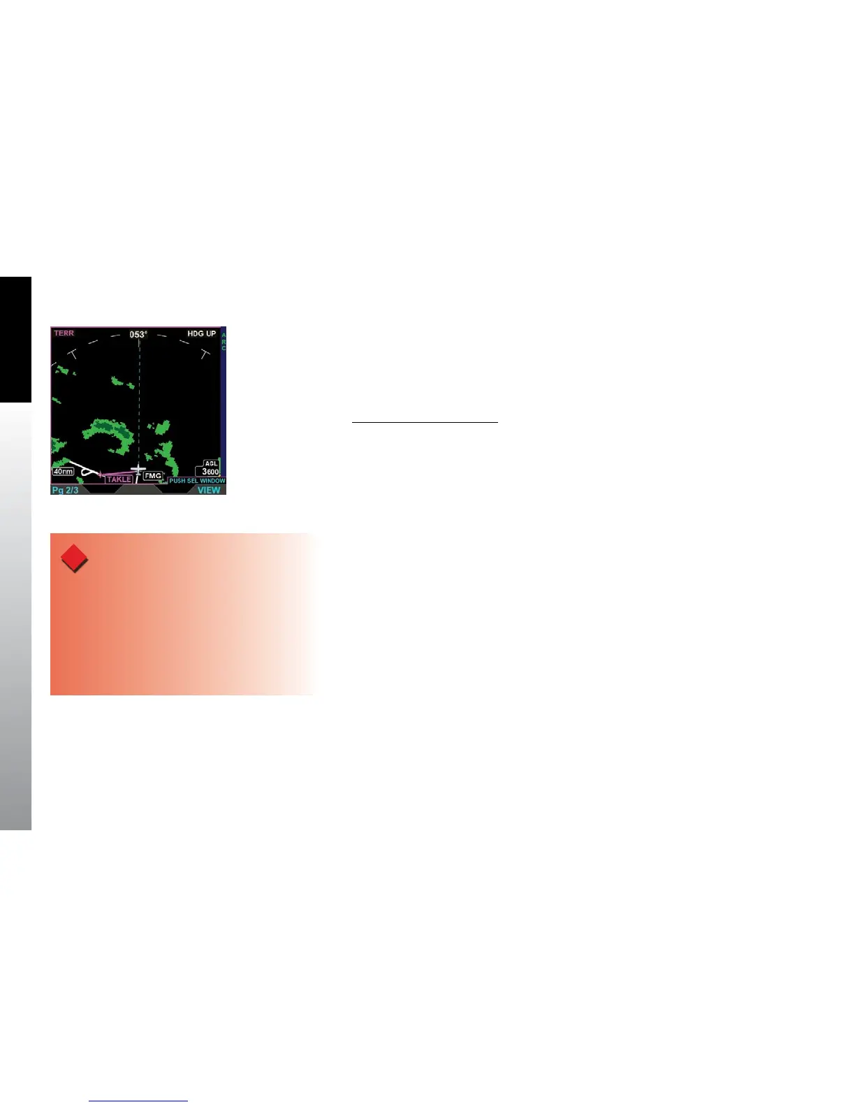
5.3.1. Terrain and Obstructions
Relative terrain is displayed on a black background, with a 360° or ARC range ring, and is
overlayed by the current ight plan if available. The displayable range is 5 – 100 nm with
a default display of 15 nm (Figure 5-69).
Change Terrain Range Ring
• Press the 360/ARC Hot Key to select a dierent range ring.
Terrain VIEW is oriented Heading-Up with the aircraft’s magnetic heading aligned with
the vertical axis of the display. The label HDG UP displays in the upper right corner of
the display and the current heading is displayed in the upper middle of the display. If
current heading is invalid or unavailable the current heading from the EFD1000 PFD or
the current track from the GPS system is used.
The EFD1000/500 MFD uses information from the Jeppesen Database to display terrain
data. If the database information, altitude, GPS position, and/or GPS track are invalid all
terrain and obstacle data is removed from the display. If terrain information is invalid or
unavailable, cyan is shown in place of the invalid or unavailable terrain
Terrain and obstruction heights in the database are MSL measurements based on
barometric pressure. The EFD1000/500 MFD uses the GPS position and MSL altitude
of the aircraft to calculate and predict a picture of the surrounding terrain and
obstructions relative to the aircraft’s ight path.
Figure 5-69
Terrain VIEW Showing an
ARC Range Ring
WARNING
The Terrain and Obstruction information provided
is based on elevation information from a third party
database and contains some inaccuracies and/or
omissions. This information should only be used as an
aid to situational awareness. The information provided
should never be used for primary terrain avoidance or
navigation.