CHAPTER 5 REFERENCE GUIDE
EFD1000/500 MFD Pilot’s Guide
Page 5-66 091-00006-001 REV B
EFD1000/500 MFD Pilot’s Guide
Page 5-67091-00006-001 REV B
5.3.3. WX-500 (optional)
When congured with a WX-500 receiver the EFD1000/500 MFD displays Stormscope®
WX 500 data, oriented Heading-Up. The default display shows the 360° view, with a 200
nm range ring on a black background (Figure 5-78). The WX-500 VIEW supports an
ARC or 360° compass ranging from 20, 30, 40, 60, 80, 100 or 200 nm as selected using
the range buttons. The EFD1000/500 MFD stores the last settings selected following the
power cycle of the unit.
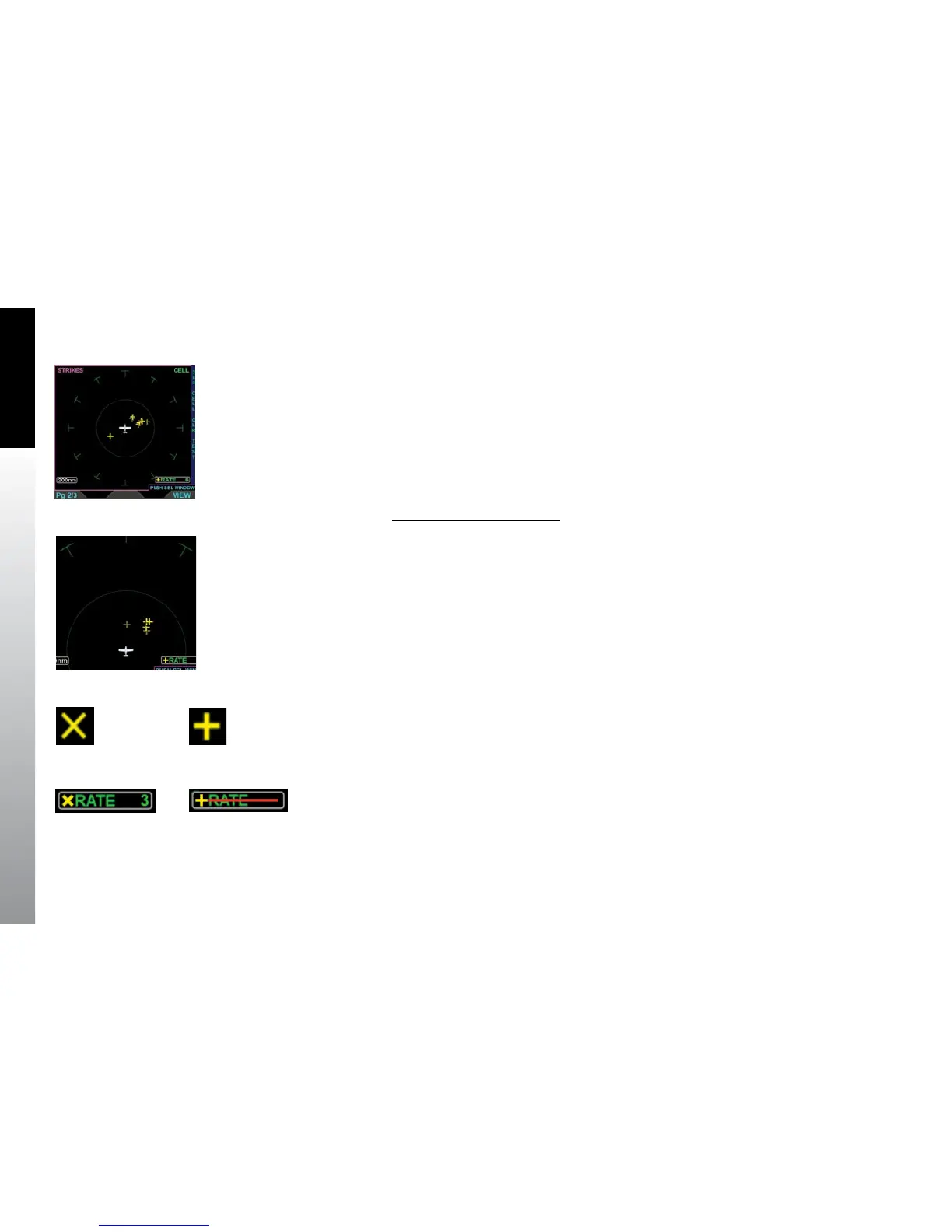
Change WX-500 Range Ring
• Press the 360/ARC Hot Key to select a dierent range ring (Figure 5-79).
According to the he Stormscope® WX-500 User Guide, the WX-500 receiver “…detects
the electric and magnetic elds generated by intra-cloud, inter-cloud, or cloud-to-
ground electrical discharges that occur within a 200 nm radius of the aircraft and sends
the resulting “discharge signals” to the processor.” The EFD1000/500 MFD displays those
discharge signals on the Stormscope® WX-500 VIEW or as an overlay on the Navigation
Map VIEW.
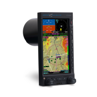
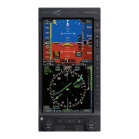
When in Strike mode, thunderstorm activity is displayed as yellow Xs (Figure 5-80)
When in Cell mode, thunderstorm activity is displayed as yellow crosses (Figure 5-81).
The current mode name is displayed in the upper right corner of the VIEW (i.e. STRK or
CELL) and the current rate is displayed in the lower right of the VIEW (Figure 5-82). Rate
will display with a red horizontal line (Figure 5-83) when:
• The receiver reports a fault error.
• Heading is invalid or unavailable.
• Spherics data is not detected.
Figure 5-78
WX-500 VIEW
in Strike Mode
Figure 5-79
WX-500 VIEW
in Cell Mode
Figure 5-80
WX-500 Strike Symbol
Figure 5-81
WX-500 Cell Symbol
Figure 5-82
WX-500 Strike Mode and Rate
Figure 5-83
WX-500 Invalid Rate