CHAPTER 3 DISPLAY & CONTROLS
EFD1000/500 MFD Pilot’s Guide
Page 3-6 091-00006-001 REV B
EFD1000/500 MFD Pilot’s Guide
Page 3-7091-00006-001 REV B
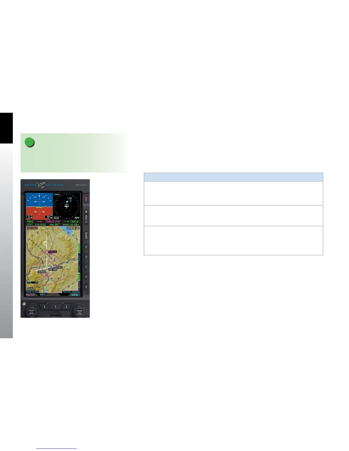
The last PAGE of the display is a three WINDOW, Thumbnail LAYOUT, and the Left Knob
label reads 3/3. The Secondary Attitude Indicator VIEW is displayed in the top left
WINDOW, Dedicated Terrain VIEW in the top right WINDOW, and VFR Navigation Map
VIEW in the bottom WINDOW (Figure 3-7).
Table 3-3 lists the VIEWS that will display in each of the Thumbnail LAYOUT WINDOWS:
Window View
Left WINDOW
• Terrain (TERR)
• Trac (TRFC)
• WX-500 (STRIKES)
• Secondary Attitude Instrument (EFD1000 MFD only)
Right
WINDOW
• Terrain (TERR)
• Trac (TRFC)
• WX-500 (STRIKES)
Bottom
WINDOW
• Navigation Map (NAV MAP)
• Terrain (TERR)
• Trac (TRFC)
• WX-500 (STRIKES)
• Data Link Weather (WEATHER)
Table 3-3 Thumbnail LAYOUT WINDOW Supported VIEWs
Figure 3-7
EFD1000/500 MFD PAGE 3/3
NOTE
If a sensor is not congured in the Installation Menu
(i.e., trac, WX-500, or EWR50) the associated sensor
VIEW shall not be displayed or selectable.