EFD1000/500 MFD Pilot’s Guide
Page PB 091-00006-001 REV B
EFD1000/500 MFD Pilot’s Guide
Page xxvii091-00006-001 REV B
Conventions
The following conventions, denitions, terminology and colors are used
in this manual and the EFD1000 PFD.
Covered Functionality
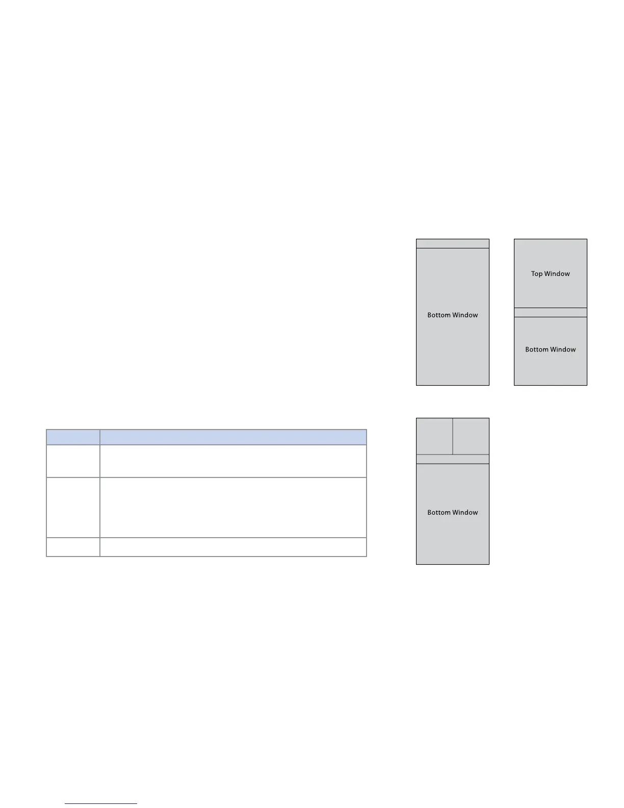
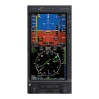
This guide covers all the functionality available in the EFD1000 MFD and EFD500 MFD.
The EFD500 MFD does not include an AHRS and ADC sensor, Secondary HSI, and does
not support Reversionary mode. See Aspen Avionics document number 091-00005-001
EFD1000 PFD Pilot’s Guide for complete instructions on the EFD1000 PFD.
Terminology
This guide uses the terminology listed in Table 1 when referring to specic parts of the
EFD1000/500 MFD. Refer to Chapter 5, Reference Guide for an in-depth discussion
and step-by-step instructions for all the available functionality of the EFD1000/500 MFD.
Term Denition
PAGE
A PAGE is the arrangement of information shown on the screen of the
EFD1000/500 MFD. There are three pages available with the MFD. Each PAGE is
based on one of the following three LAYOUTs.
LAYOUT
The LAYOUT denes how WINDOW and VIEW information are arranged on the
EFD1000/500 MFD screen. The pilot can select a one, two or thee WINDOW
display by rotating the Left Knob. The PAGE LAYOUT cannot be changed;
however, the pilot can customize the VIEW displayed in a WINDOW. The
EFD1000/500 MFD displays information in one of three PAGE LAYOUTS as
shown in Figure 1 – Figure 3.
WINDOW
A WINDOW is a section of a PAGE where a VIEW is displayed, analogous to a
window on a computer. The WINDOW “holds” the current VIEW.
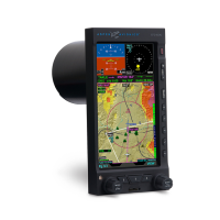
Figure 1
Full Screen LAYOUT
Figure 2
Split Screen LAYOUT
Figure 3
Thumbnail LAYOUT
Data Bar
Data Bar
Data Bar