CHAPTER 5 REFERENCE GUIDE
EFD1000/500 MFD Pilot’s Guide
Page 5-60 091-00006-001 REV B
EFD1000/500 MFD Pilot’s Guide
Page 5-61091-00006-001 REV B
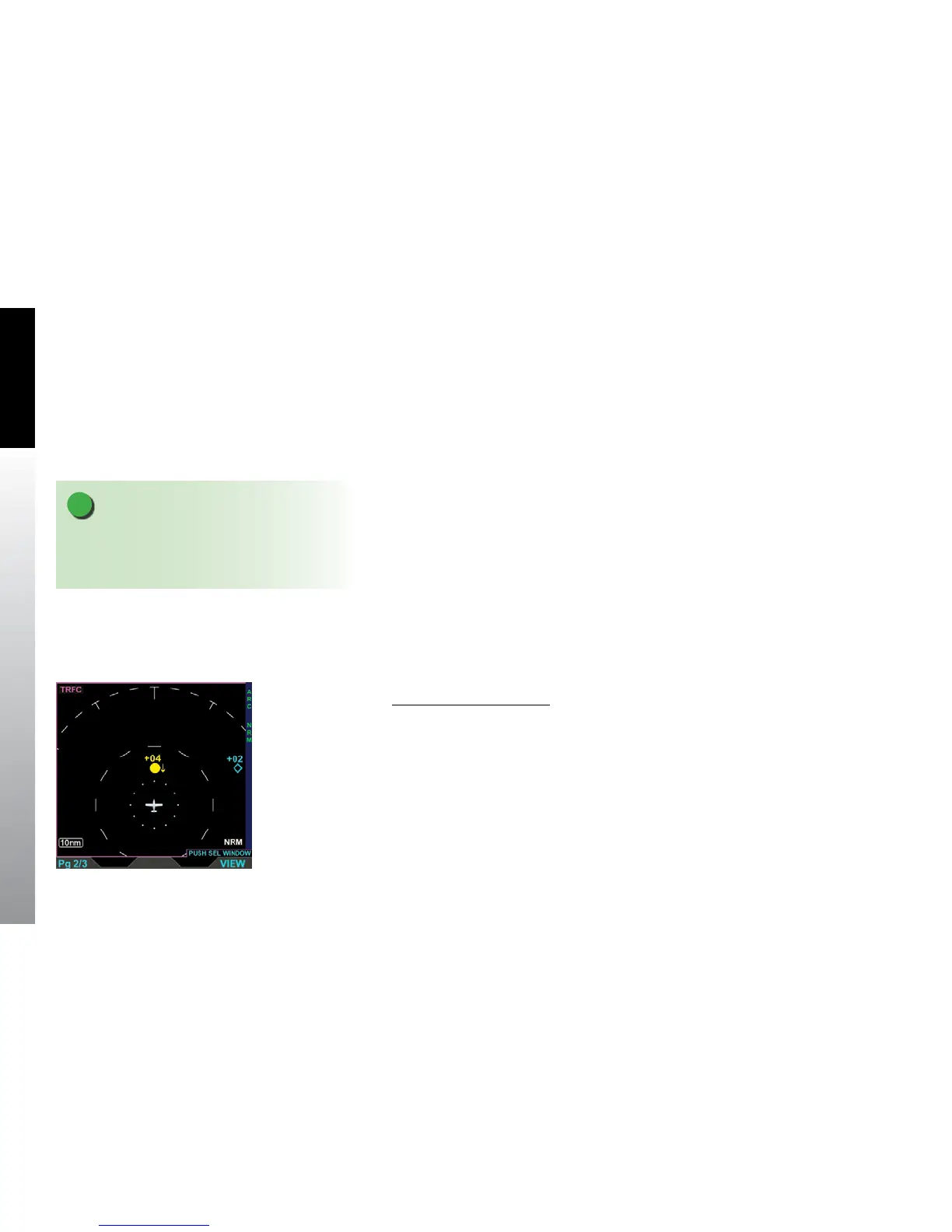
5.3.2.1. Trac Display
The Trac VIEW is oriented Heading-Up, with either a 360° or ARC compass view, with
a white outer and inner range ring. The pilot selects the compass view by pressing
the 360/ARC Hot Key; 360° is the default when not previously set. The range is pilot-
selectable with the outer-range ring and inner-range ring representing the following
range selections from the ownship position:
• 2 nm outer-range ring
• 3 nm outer-range ring and 2 nm inner-range ring
• 5 nm outer-range ring and 2 nm inner-range ring
(Default if not previously set)
• 10 nm outer-range ring, 5 nm middle-range ring,
and 2 nm inner-range ring
• 15 nm outer-range ring and 7.5 nm inner-range ring
• 20 nm outer-range ring and 10 nm inner-range ring
• 30 nm outer-range ring and 15 nm inner-range ring
• 40 nm outer-range ring and 20 nm inner-range ring
Change Trac Range Ring
• Press the 360/ARC Hot Key to select a dierent range ring (Figure 5-72).
NOTE
The 2 nm inner-range ring has dots at the clock
positions; all other inner-range rings have dashes at
the clock positions. .
Figure 5-72
Trac VIEW Showing an
ARC Range Ring