3-65
Confidential
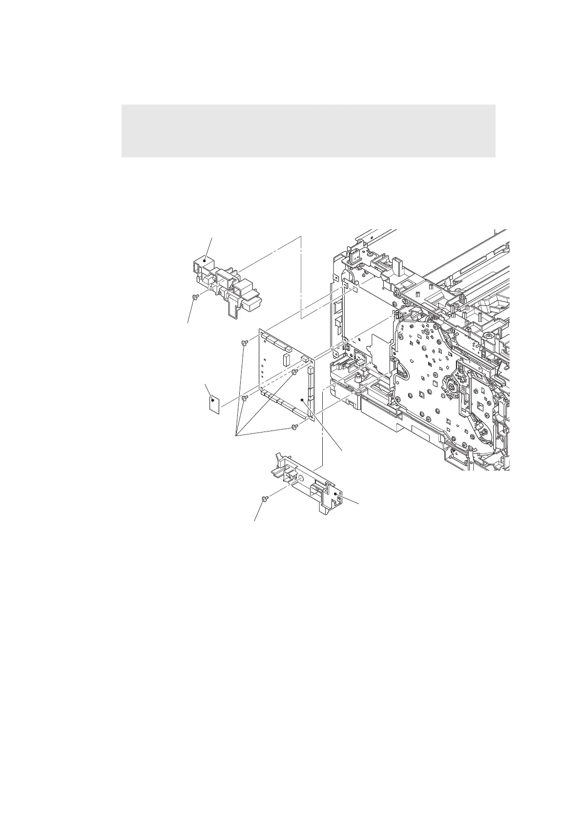
(3) Release each harness and flat cable securing fixture from each veil cover.
(4) Remove the screw cup M3x8 (black) screw, and remove the veil cover upper.
(5) Disconnect the wireless LAN PCB. (Wireless LAN models only)
(6) Remove the screw cup M3x8 (black) screw, and remove the veil cover lower.
(7) Remove the four screw cup M3x8 (black) screws, and remove the main PCB ASSY.
Fig. 3-52
Harness routing: Refer to “3. Left side of the machine (Common to all models)”.
Note:
• For touch panel models, pull out the connector harness from the hole of the veil
cover upper.
Main PCB ASSY
Screw cup M3x8 (black)
Screw cup M3x8 (black)
Screw cup M3x8 (black)
Veil cover upper
Veil cover lower
Wireless LAN PCB
(Wireless LAN models only)
 Loading...