7-12
Confidential
■ Common to all models
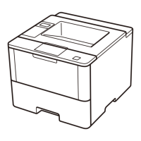
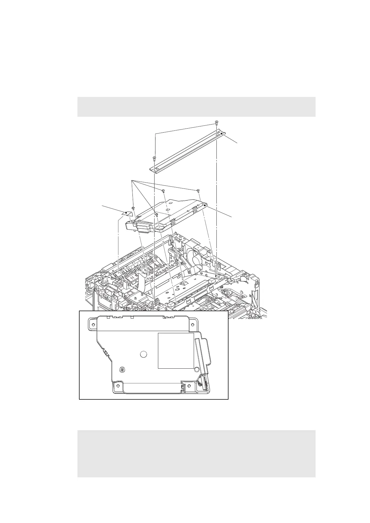
(18) Remove the two taptite bind B M4x12 screws, and remove the top bar. (Touch panel
models)
(19) Disconnect the laser unit flat cable from the laser unit, and release it from the securing
fixtures.
(20) Remove the four taptite cup S M3x8 SR screws, and remove the laser unit.
Fig. 7-17
Harness routing:
Refer to “3. Left side of the machine (Common to all models), 6. Rear side of the machine”.
Note:
• Be careful not to touch the lens of the laser unit.
Assembling Note:
• When attaching the laser unit, tighten the screws in the following order: upper right,
lower right, lower left and upper left.
• When connecting flat cables, do not insert them at an angle. After insertion, check
that the cable is not at an angle.
Laser unit flat cable
Laser Unit
1
2
3
4
Top bar
(Touch panel models)
Taptite bind B M4x12
Taptite cup S M3x8 SR
 Loading...