2-210
COPYRIGHT
©
2001 CANON INC. 2000 2000 2000 2000 CANON CLC5000 REV.0 JAN. 2001
CHAPTER 2 NEW FUNCTIONS
SL1
SL3
+24V
LDCRSL1
J204A-7
-4
SL4
+24V
LDCRSL2
J204A-9
-8
SL5
+24V
UDCRSL1
J204A-11
-10
SL6
+24V
UDCRSL2
J204A-13
-12
+24V
FLPSL1
J204A-5
-4
J1
+24V
+24V
+24V
+24V
SW
J302-1
J205B-2
FT5
FT6
FT2
FT3
FT4
FT1
-2
-3
-4
-1
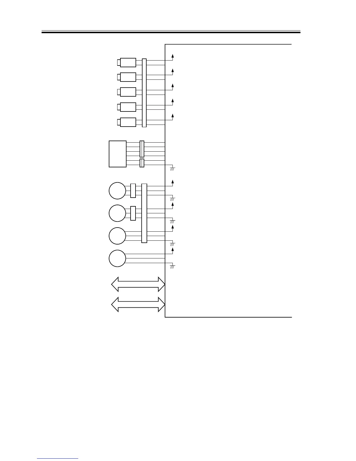
SW1
J532
J530
Flapper solenoid
Downward curl removing
solenoid 1
Downward curl removing
solenoid 2
Upward curl removing
solenoid 1
Upward curl removing
solenoid 2
Cover switch
Cooling fan 1
Cooling fan 2
Cooling fan 3
Cooling fan 4
To sorter
To copier
Buffer pass unit driver PCB
When ‘0’, the flapper solenoid
turns on.
When ‘0’, the downward curl
removing roller solenoid 1 turns on.
When ‘0’, the downward curl
removing roller solenoid 2 turns on.
When ‘0’, the upward curl removing
roller solenoid 1 turns on.
When ‘0’, the upward curl removing
roller solenoid 2 turns on.
When the front cover is closed, ‘0’.
When ‘1’, the cooling fan 1 does not
rotate.
When ‘1’, the cooling fan 2 does not
rotate.
When ‘1’, the cooling fan 3 does not
rotate.
When ‘1’, the cooling fan 4 does not
rotate.
Note: The asterisk (*) indicates negative logic.
FAN3LOCK
+24V
J204B-7
-9
-8
FAN4LOCK
+24V
J204B-10
-12
-11
FM3
FM4
FAN1LOCK
+24V
J204B-1
-3
-2
J509 J2
FAN2LOCK
+24V
J204B-4
-6
-5
J510
FM1
FM2
F02-901-04