2-244
COPYRIGHT
©
2001 CANON INC. 2000 2000 2000 2000 CANON CLC5000 REV.0 JAN. 2001
CHAPTER 2 NEW FUNCTIONS
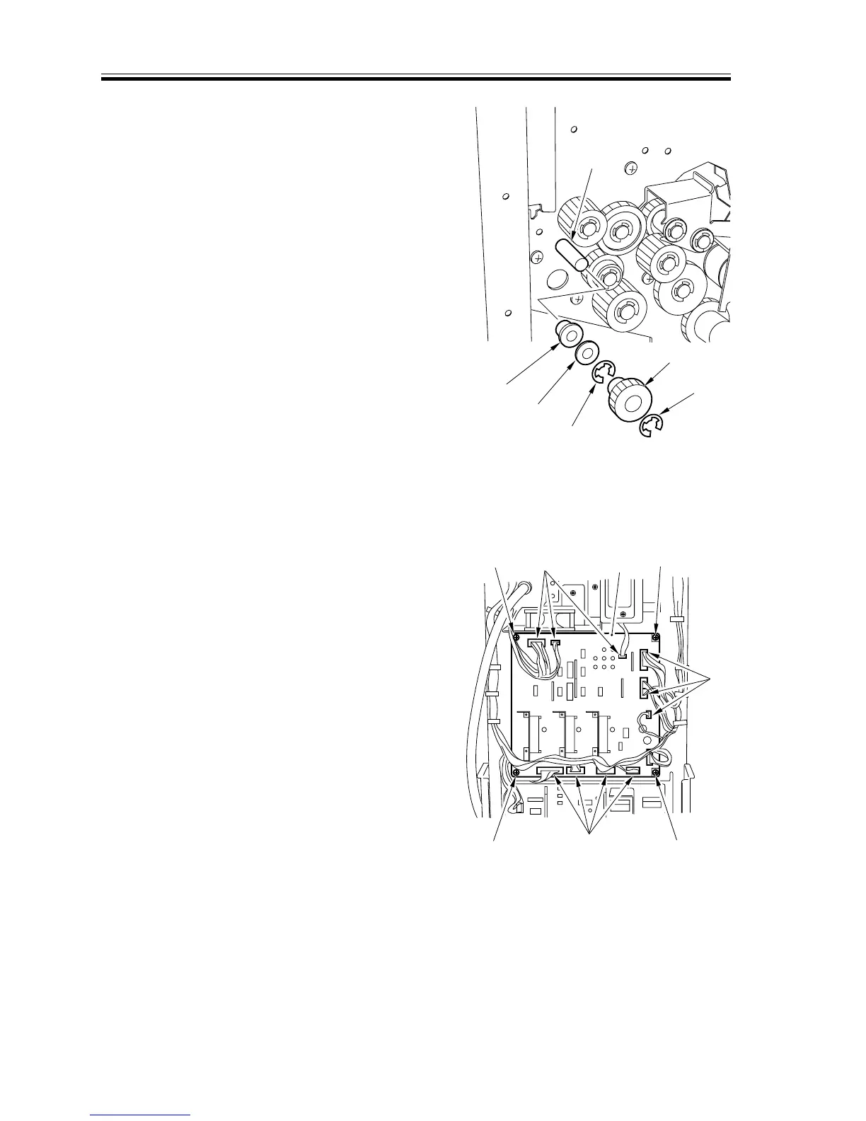
10) Remove the two E-rings [12], gear [13],
washer [14], and bearing [15] at the
rear; then, detach the feed roller (upper
guide) [16].
F02-907-30
9.7.3 PCBs
Removing the Buffer Pass Driver PCB
1) Remove the rear cover.
2) Remove the four screws [1], and dis-
connect the 11 connectors [2]; then, de-
tach the buffer pass driver PCB [3].
F02-907-31
[1] [1]
[1]
[1]
[2]
[2]
[2]
[3]
[12]
[13]
[12]
[16]
[15]
[14]



 To Next Page