COPYRIGHT
©
2001 CANON INC.
2000 2000 2000 2000
CANON CLC5000 REV.0 JAN. 2001
CHAPTER 3 INSTALLATION
3-8
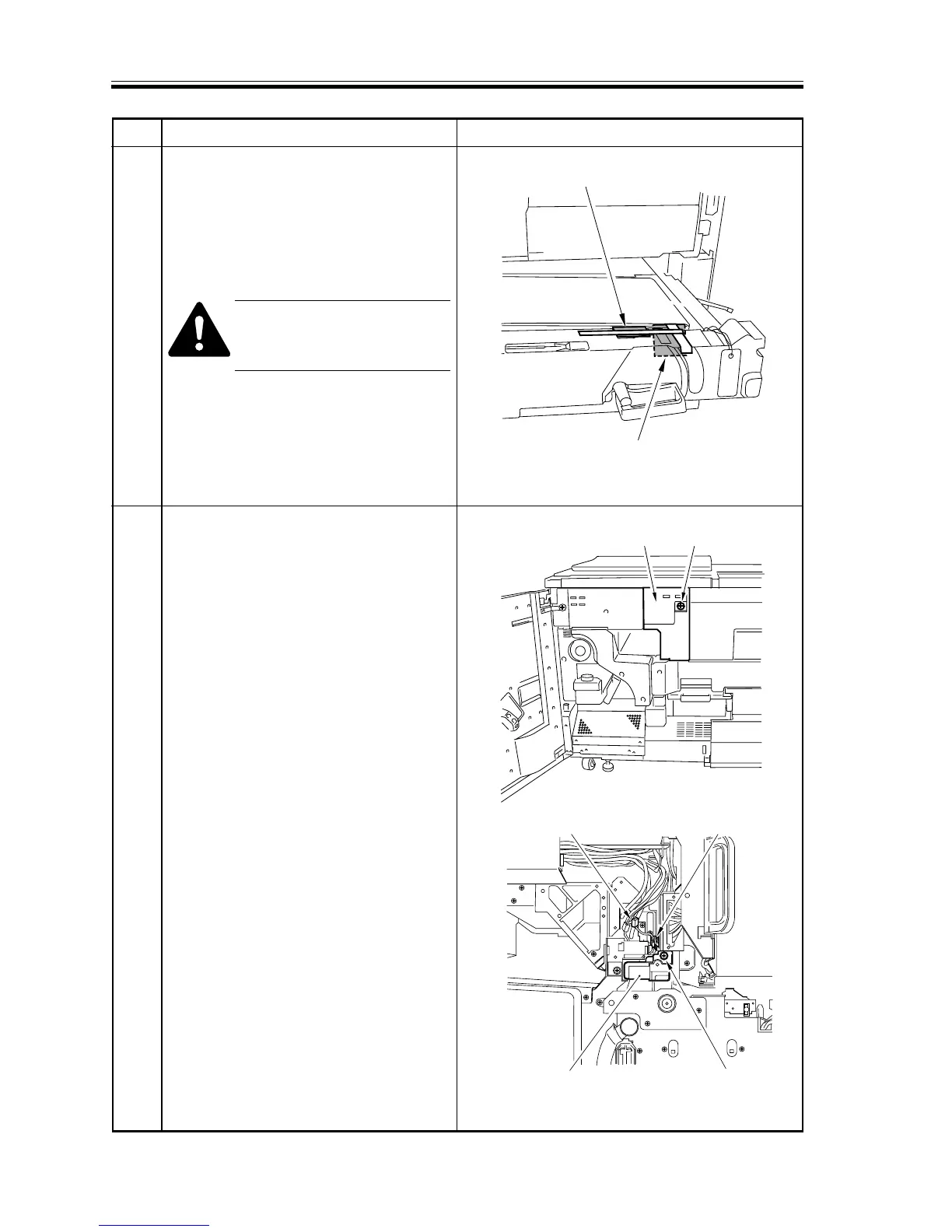
Cushioning material
Cushioning material
Hopper assembly
left cover
screw
Wire saddleConnector
Screw
Separation charging
assembly
Step Work Remarks
7 Release the lever of the transfer unit,
and slide out the transfer unit; then,
remove the fixing tape used to keep the
jam tweezers in place and the fixing
tape used to keep the transfer belt in
place at the rear.
Do not remove the tag found at
the front of the pre-transfer
cover.
Remove all fixing tape from the pre-
transfer cover.
8 • Remove the screw, and detach the
hopper assembly left cover.
• Remove the screw, and disconnect the
connector, and open the wire saddle;
then, detach the separation charging
assembly.
F03-302-03
F03-302-04
F03-302-05