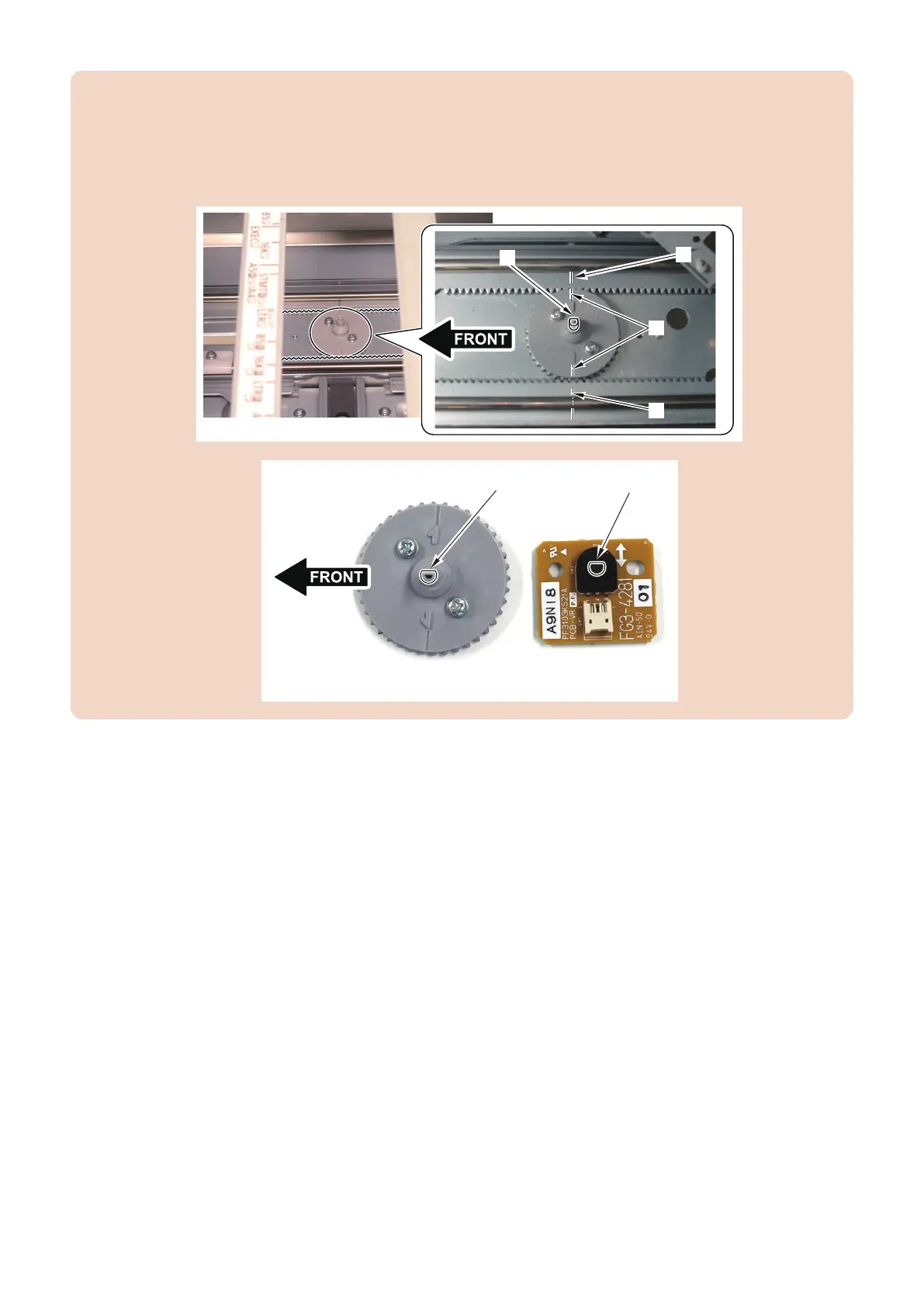
CAUTION:
• When assembling, check that the engraved mark [B] on the Pinion Gear and the engraved mark [A] on the Rack Gear
are met in line.
• When the engraved marks are not met in line, remove the Pinion Gear, and slide the Side Guide Plate to make the D-
cut face [C] of the Pinion Gear as shown in the figure and align the engraved marks to install the Pinion Gear.
• Align the direction of the D-cut face [C] on the Pinion Gear and the Hole [D] on the Deck Size Detection PCB to install.
■ Handling after Parts Replacement
1. Turn ON the main power switch of the host machine.
2. To register the width of A4 paper.
1. Set the A4 paper in the deck to adjust and align it with the side guide plate.
2. Execute the following item on the service mode.
COPIER> FUNCTION> CST> MDK1-A4/MDK4-A4 : Upper (M Deck/Sec M Deck)
COPIER> FUNCTION> CST> MDK2-A4/MDK5-A4 : Middle (M Deck/Sec M Deck)
COPIER> FUNCTION> CST> MDK3-A4/MDK6-A4 : Lower (M Deck/Sec M Deck)
3. Select the item, and then press OK key.
4. After automatic adjustment, the value is stored in the following item.
COPIER> ADJUST> CST-ADJ >MDK1-A4/MDK4-A4 : Upper (M Deck/Sec M Deck)
COPIER> ADJUST> CST-ADJ> MDK2-A4/MDK5-A4 : Middle (M Deck/Sec M Deck)
COPIER> ADJUST >CST-ADJ> MDK3-A4/MDK6-A4 : Lower (M Deck/Sec M Deck)
4. Parts Replacement and Cleaning
141