■ Procedure
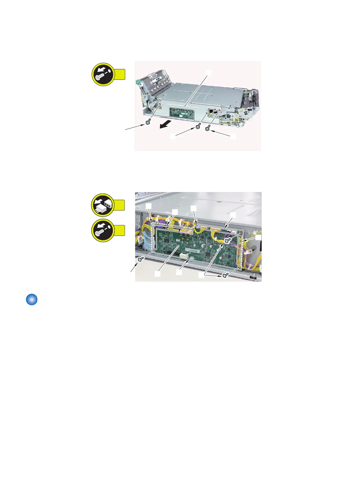
1. Remove the PCB Cover [1].
• 4 Screws [2]
2. Remove the Through Path Unit PCB [1].
• 13 Connectors [2]
• 3 Screws [3]
• 3 Locking Supports [4]
13x
3x
[1]
[2]
[2]
[2]
[3]
[3]
[4]
[4]
[4]
Removing the LED PCB 1 (PCB402)
■ Preparation
1. Remove the Right Connection Unit. “Removing the Right Connection Unit” on page 91
2. Remove the Deck Rear Middle Cover.“Removing the Deck Rear Middle Cover” on page 79
3. Remove the Through Path Unit. “Removing the Through Path Unit” on page 93
4. Remove the Through Path Inlet Unit.“Removing the Through Path Inlet Unit” on page 96
4. Parts Replacement and Cleaning
145