ITEM SPECIFICATION (mm)
Valve Outer Diameter
Intake Valve 5.98 ± 0.008
Exhaust Valve 5.98 ± 0.008
Valve Guide Inner Diameter
Intake Valve 5.4 ± 0.1
Exhaust Valve 5.4 ± 0.1
Fringe Thickness On Top Of Valve
Intake Valve 0.3 ± 0.15
Exhaust Valve 0.3 ± 0.15
Valve Tilt Angle
Intake Valve 65°
Exhaust Valve 68°
Valve Height
Intake Valve 107.998
Exhaust Valve 106.318
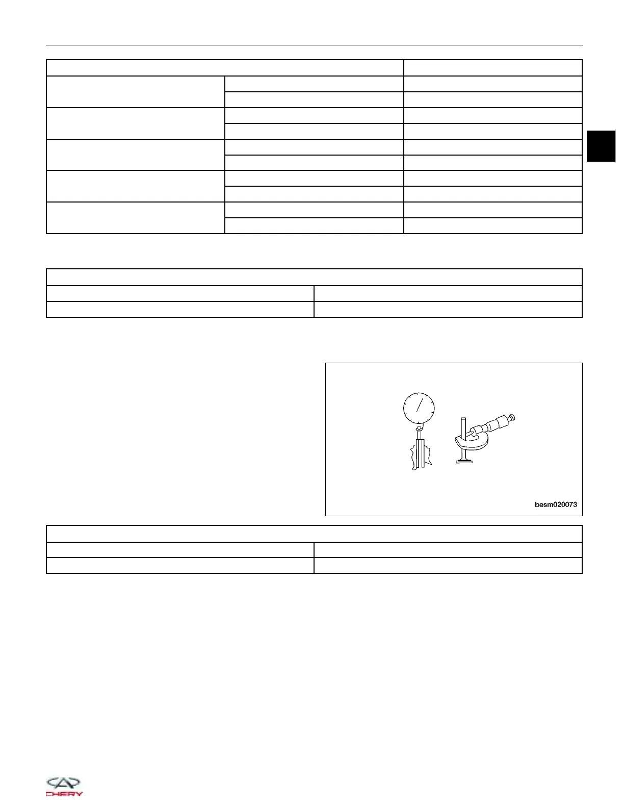
• Measure valve deflection.
VALVE DEFLECTION LIMIT (DIAL GAUGE READING)
Intake Valve 0.02 mm
Exhaust Valve 0.04 mm
• If it exceeds the limit, check valve to valve guide clearance.
− Measure valve stem diameter and valve guide inner diameter.
− Check that clearance is within specification.
− If it exceeds the limit, replace valve or valve
guide.
VALVE TO VALVE GUIDE CLEARANCE STANDARD
Intake Valve 0.012 - 0.043 mm
Exhaust Valve 0.032 - 0.063 mm
Assembly
1. Install the valves into the cylinder head (larger diameter on intake side).
CYLINDER HEAD UNIT REPAIR
BESM020073
02
02–75
Chery Automobile Co., Ltd.