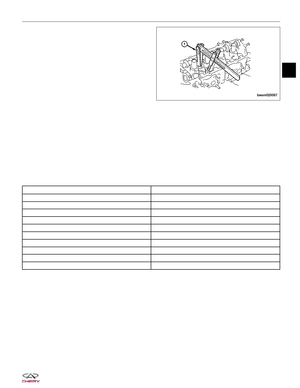
7. Using a valve spring compressor CH-20018 (1),
compress the valve springs.
8. Install the valve keepers.
9. Strike the valve stem lightly with a plastic hammer after installation to verify proper assembly.
10. Install valve tappets in the head.
11. Install the camshafts.
Installation Notes:
• Coat the valve oil seals with engine oil.
Camshaft
Specifications
Camshaft Specifications
DESCRIPTION SPECIFICATION (mm)
Intake Cam Lobe Height 37.11
Exhaust Cam Lobe Height 37.09
Journal #1 Outer Diameter 31.934 - 31.95
Journal #2, #3, #4, #5, Outer Diameter 23.947 - 23.96
Cam Bearing #1 Inner Diameter 32 - 32.025
Cam Bearing #2, #3, #4, #5, Inner Diameter 24 - 24.021
Journal #1 Clearance 0.05 - 0.090
Journal #2, #3, #4, #5 Clearance 0.04 - 0.074
Intake Camshaft Axial Clearance 0.15 - 0.20
Exhaust Camshaft Axial Clearance 0.15 - 0.20
CYLINDER HEAD UNIT REPAIR
BESM020067
02
02–69
Chery Automobile Co., Ltd.