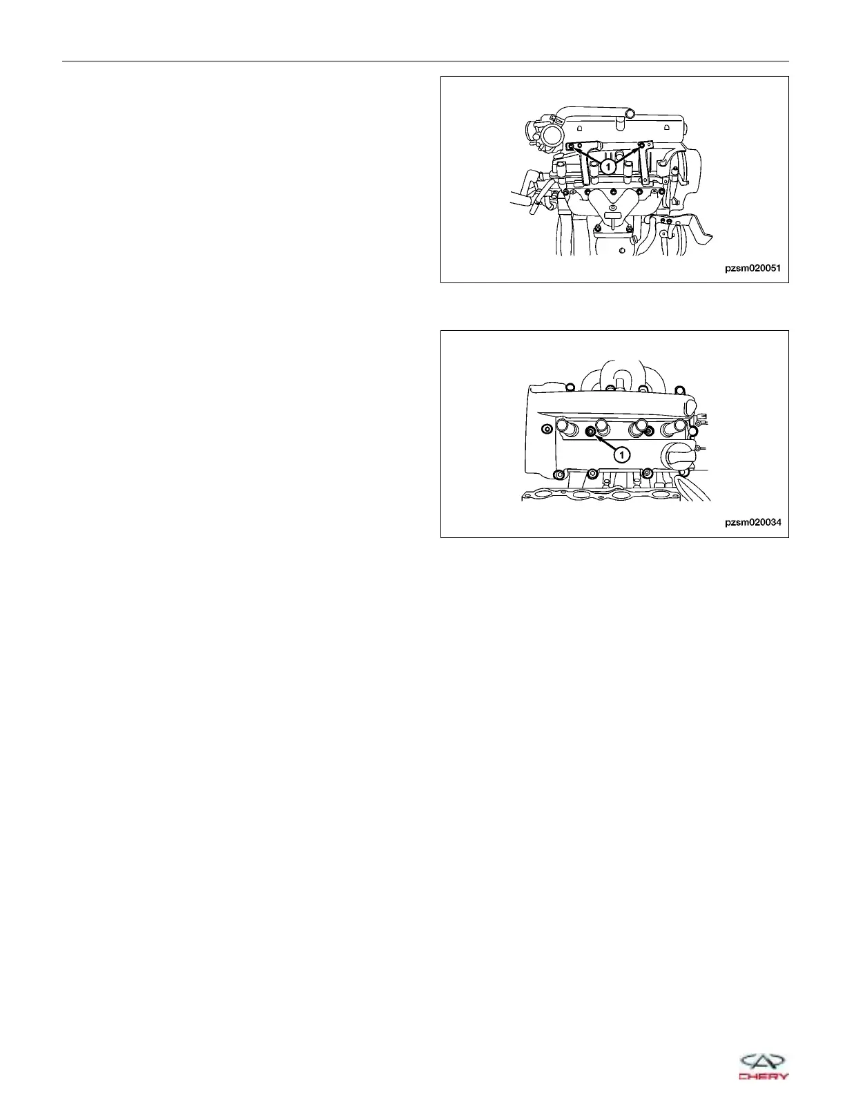
12. Remove the two intake manifold bracket retaining
bolts (1).
13. Remove the intake manifold (See Intake manifold Removal & Installation in Section 02 Engine).
14. Remove the twelve cylinder head cover bolts (1).
(Tighten: Cylinder head cover bolts to 10 ± 2 N·m)
15. Remove the cylinder head cover.
16. Installation is in the reverse order of removal.
Camshaft
Removal & Installation
NOTE :
The following special tools are required to perform the repair procedure:
• CH-20002 - Camshaft Seal Installer
• CH-20010 - Camshaft Holder
1. Remove the accessory drive belt (See Accessory Drive Belt Removal & Installation in Section 02 Engine).
2. Remove the engine timing belt (See Engine Timing Belt Removal & Installation in Section 02 Engine).
3. Remove the cylinder head cover (See Cylinder Head Cover Removal & Installation in Section 02 Engine).
ON-VEHICLE SERVICE
PZSM020051
PZSM020034
02–22
Chery Automobile Co., Ltd.