7. Raise and support the vehicle.
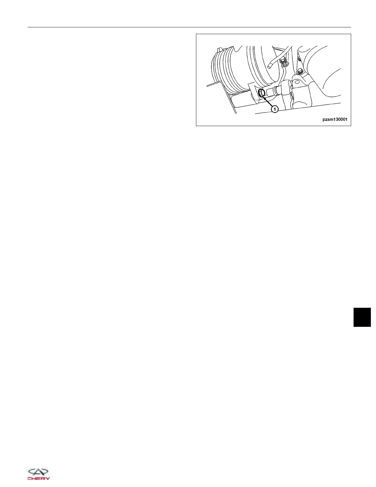
8. Remove the A/C compressor lower mounting bolt
(1).
(Tighten: A/C compressor lower mounting bolt to 20
+ 5 N·m)
9. Carefully remove the A/C compressor.
10. Installation is in the reverse order of removal.
Installation Notes:
• Lubricate new rubber O-ring seals with clean refrigerant oil and install them and new gaskets onto the refriger-
ant line fittings.
• Use only the specified O-rings as they are made of a special material for the R-134a system.
• Use only refrigerant oil of the type recommended for the A/C compressor in the vehicle.
• Recharge the A/C system (See A/C System Evacuation and Recharge in Section 13 Heating and Air Condition-
ing).
Evaporator
Description
The evaporator coil is located in the HVAC housing, under the instrument panel. The evaporator coil is positioned in
the HVAC housing so that all air that enters the housing must pass over the fins of the evaporator before it is dis-
tributed through the system ducts and outlets. However, air passing over the evaporator coil fins will only be condi-
tioned when the compressor is engaged and circulating refrigerant through the evaporator coil tubes.
Operation
Refrigerant enters the evaporator from the orifice tube as a low-temperature, low-pressure liquid. As air flows over
the fins of the evaporator, the humidity in the air condenses on the fins, and the heat from the air is absorbed by the
refrigerant. Heat absorption causes the refrigerant to boil and vaporize. The refrigerant becomes a low-pressure gas
before it leaves the evaporator. The evaporator core housing directs airflow from the blower motor through the evap-
orator core and heater core. All airflow from the blower motor passes through the evaporator core. The airflow is then
directed through or around the heater core by the temperature blend door(s). An electric actuator-positioned temper-
ature blend door to direct airflow through or around the heater core.
Removal & Installation
1. Evacuate the A/C system (See A/C System Evacuation and Recharge in Section 13 Heating and Air Condition-
ing).
ON-VEHICLE SERVICE
PZSM130001
13
13–37
Chery Automobile Co., Ltd.