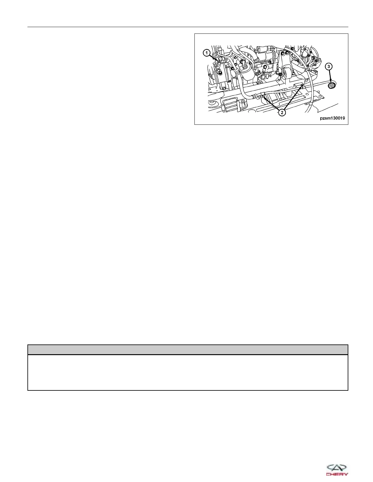
7. Remove the retaining bolt (1) connecting the A/C
suction line to the compressor.
8. Loosen the retaining nut (3) connecting the A/C
suction line to the condenser.
9. Remove the two A/C suction line retaining bolts (2)
from the clamps.
10. Plug or tape over the opened refrigerant line fittings and the evaporator ports.
11. Remove the A/C suction line assembly from the engine compartment.
12. Installation is in the reverse order of removal.
Installation Notes:
• Lubricate new rubber O-ring seals with clean refrigerant oil and install them and new gaskets onto the refriger-
ant line fittings.
• Use only the specified O-rings as they are made of a special material for the R-134a system.
• Use only refrigerant oil of the type recommended for the A/C compressor in the vehicle.
• Recharge the A/C system (See A/C System Evacuation and Recharge in Section 13 Heating and Air Condition-
ing).
Heater Core
Description
The heater core is located in the HVAC housing. The heater core is a heat exchanger made of rows of tubes with
fins and is positioned within the air distribution housing so that only the selected amount of air entering the housing
passes through the heater core before it is distributed through the heating-A/C system ducts and outlets. One end of
the heater core is fitted with a tank that includes the fittings for the heater core tubes. The heater core can only be
serviced by removing the HVAC housing from the vehicle.
Operation
Engine coolant is circulated through the heater hoses to the heater core at all times. As the coolant flows through the
heater core, heat is removed from the engine and is transferred to the heater core tubes and fins. Air directed
through the heater core picks up the heat from the heater core fins. The blend-air door allows control of the heater
output air temperature by regulating the amount of air flowing through the heater core. The blower motor speed con-
trols the volume of air flowing through the HVAC housing.
Removal & Installation
WARNING!
Always allow the engine to cool before opening the cooling system. Do not loosen the coolant pressure relief
cap when the engine is operating or the cooling system is hot. The cooling system is under pressure; steam and
hot liquid can come out forcefully when the cap is loosened slightly. Failure to follow these instructions may
result in serious personal injury.
1. Drain the cooling system (See Cooling System Draining Procedure in Section 06 Cooling System).
ON-VEHICLE SERVICE
PZSM130019
13–44
Chery Automobile Co., Ltd.
 Loading...