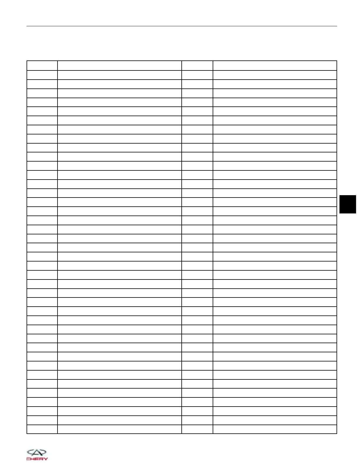
Automated Manual Transaxle (AMT) Control Module Connector Pin-Out Table
AMT Control Module Pin-Out Table
PIN CIRCUIT INDENTIFICATION PIN CIRCUIT INDENTIFICATION
1 Power Ground 41 -
2 Power Ground 42 -
3 Gear 4 Command 43 Clutch Command
4 - 44 Gear 2 Command
5 - 45 CAN-H
6 - 46 -
7 CAN-L 47 -
8 - 48 -
9 - 49 Diagnostic
Line
10 - 50 Clutch Speed Negative
11 - 51 Shift Position Sensor
12 - 52 Clutch Position Sensor
13 - 53 -
14 - 54 -
15 - 55 -
16 - 56 -
17 - 57 -
18 - 58 -
19 CAN-H 59 External Sensor Ground
20 - 60 -
21 - 61 -
22 - 62 -
23 - 63 -
24 - 64 -
25 - 65 External Sensor Ground
26 Gear Selection Lever Bit 0 66 External Sensor Ground
27 Battery 67 Gear Selection Lever Bit 1
28 Ignition Switch 68 Gear Selection Lever Bit 3
29 Gear 3 Command 69 Brake Lamp Input
30 - 70 -
31 Hydraulic Pump Relay Command 71 -
32 Gear 1 Command 72 -
33 CAN-L 73 External Sensor Power Supply
34 - 74 Gear Selection Lever Bit 2
35 - 75 -
36 - 76 Cranking Input Switch
37 - 77 ECO/Normal Mode Input Switch
38 Clutch Speed Positive 78 Door Switch Input
39 Gear Position Sensor 79 External Sensor Power Supply
40 Hydraulic Pressure Sensor 80 -
GENERAL INFORMATION
08
08–59
Chery Automobile Co., Ltd.

 Loading...