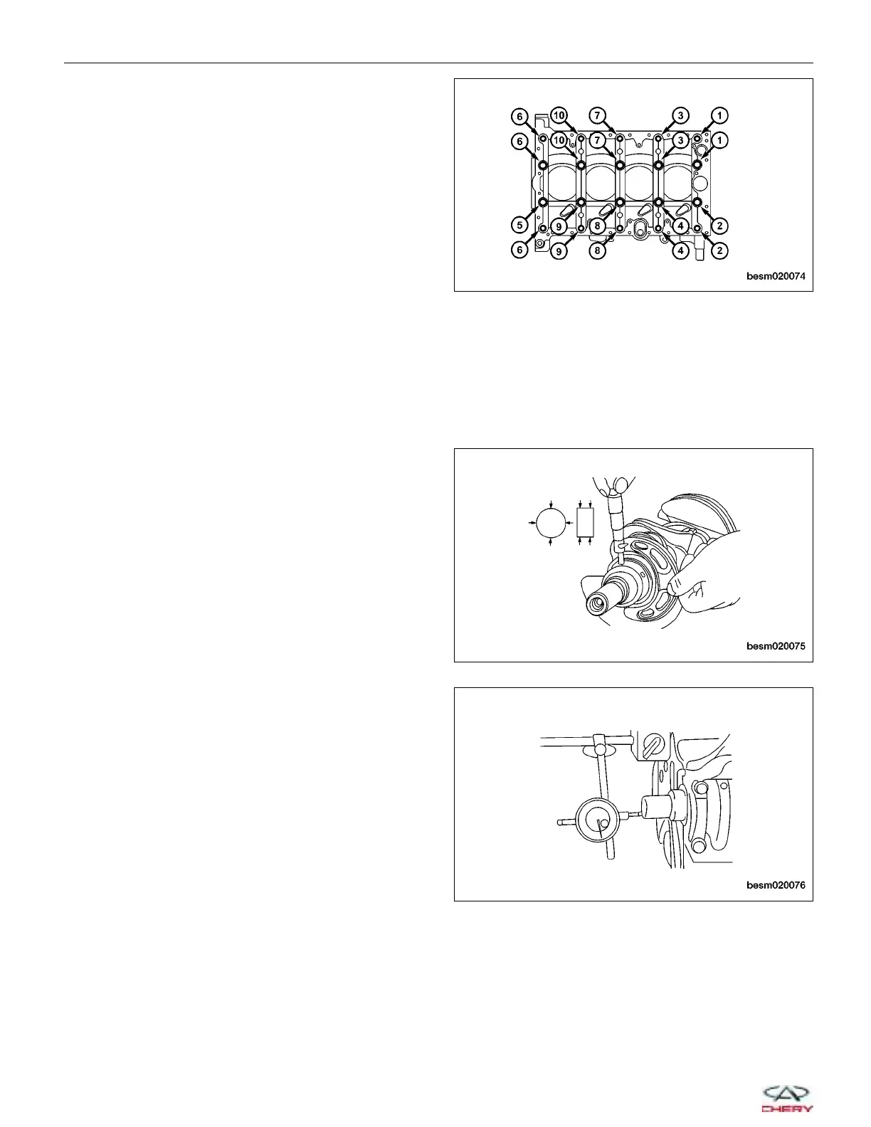
4. Remove the 20 lower cylinder block bolts in the
sequence shown.
NOTE: Before loosening the lower cylinder block
bolts, measure the crankshaft side clearance.
5. Remove the lower cylinder block.
6. Remove the crankshaft.
7. Remove the main bearings and thrust bearings from the upper cylinder block and lower cylinder block.
NOTE: If reusing the bearings, identify and number the bearings so that they are assembled in the same position
and direction.
Inspection
Inspect the crankshaft rod and main journals for the fol-
lowing:
• The crankshaft main journals should be checked for
excessive wear, roundness and scoring.
• Main journal limits of roundness should be held to
0.008 mm.
• Rod journal limits of roundness should be held to
0.005 mm.
CAUTION:
DO NOT nick the crank journals or bearing
fillets.
Check the axial clearance after installation:
• Standard axial clearance should be 0.02 mm.
• Limits of axial clearance should be held to 0.30
mm.
ENGINE UNIT REPAIR
BESM020074
BESM020075
BESM020076
02–64
Chery Automobile Co., Ltd.