13. Remove the rear wheel cylinder retaining bolts (1)
and the brake tube nut (2).
14. Remove the rear wheel cylinder.
15. Installation is in the reverse order of removal.
Installation Notes:
• After installation bleed the wheel cylinder as necessary.
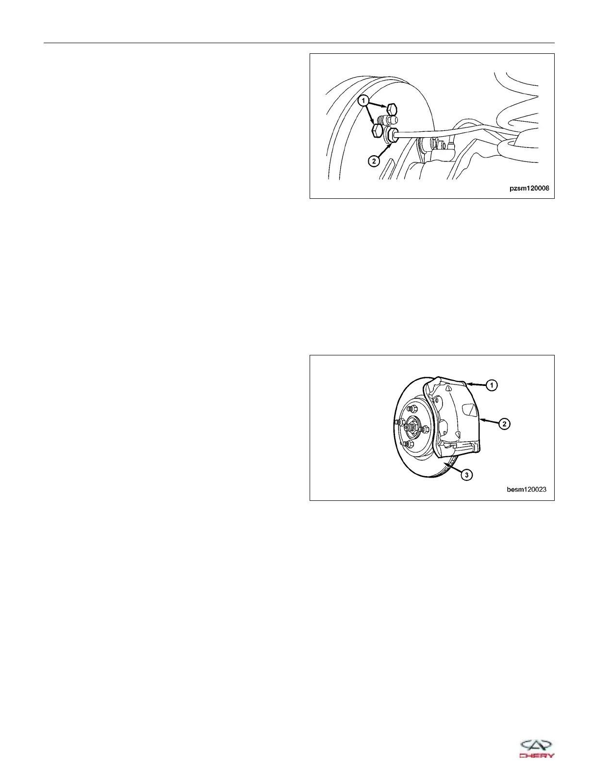
Front Brake Rotor
Removal & Installation
1. Raise and support the vehicle.
2. Remove the wheel mounting nuts and the tire and wheel assembly.
(Tighten: Wheel mounting nuts to 110 N·m)
3. Remove front caliper (2) and bracket (1) together
(See Front Caliper Removal & Installation in Sec-
tion 12 Brakes).
4. Slide the front brake rotor (3) off the hub and bear-
ing.
5. Installation is in the reverse order of removal.
Inspection
Excessive runout or wobble in a rotor can increase pedal travel due to piston knock-back. This increases guide pin
sleeve wear due to the tendency of the caliper to follow the rotor wobble.
Braking Surface Inspection
Light braking surface scoring and wear is acceptable. If heavy scoring or warping is evident, the rotor must be resur-
faced or replaced. Excessive wear and scoring of the rotor can cause improper lining contact on the rotor’s braking
surface. If the ridges on the rotor are not removed before new brake pads are installed, improper wear of the shoes
will result. Some discoloration or wear of the rotor surface is normal and does not require resurfacing when linings
are replaced. If cracks or burned spots are evident, the rotor must be replaced.
ON-VEHICLE SERVICE
PZSM120008
BESM120023
12–14
Chery Automobile Co., Ltd.