2.
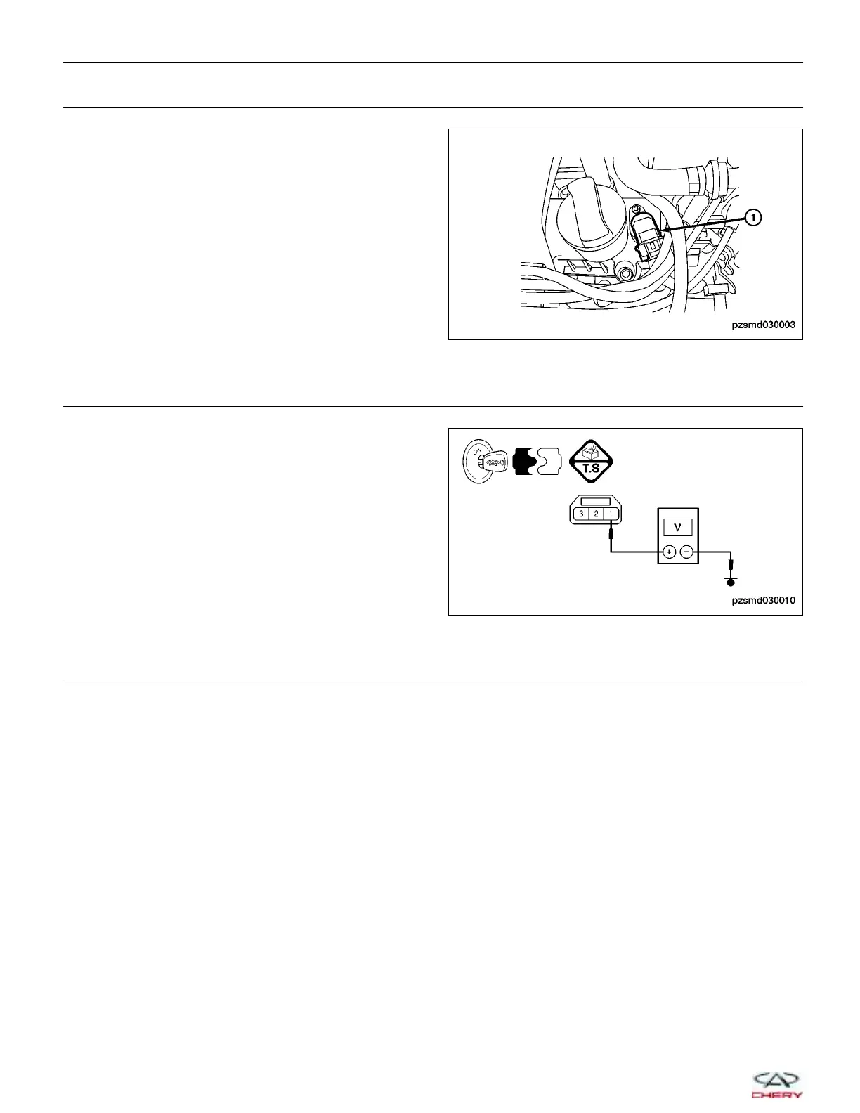
CHECK CMP SENSOR ELECTRICAL CONNECTOR
• Disconnect the CMP sensor (1) electrical connector.
• Inspect the electrical connector for damage.
Is the electrical connector OK?
Yes
>> Go to the next step.
No
>> Repair or replace the electrical connector
as necessary.
3.
CHECK THE CMP SENSOR POWER SUPPLY CIRCUIT FOR AN OPEN OR SHORT
• Turn ignition switch on.
• Check the voltage between terminal 1 and ground
in CMP sensor connector E-007 terminal side.
• Battery voltage should exist.
Is the check result normal?
Yes
>> Go to step 5.
No
>> Go to the next step.
4.
DETECT MALFUNCTIONING PART
• Check the following for a possible malfunction:
− Fuse EF5
− Main relay
− Front fuse and relay box K A-040
− Harness for an open or short between CMP sensor terminal 1 and fuse EF5
− Harness for an open or short between ECM terminal 14 and fuse EF5
• Repair or replace any malfunctioning part(s) as necessary.
• With the X-431 scan tool, read ECM DTCs.
• Refer to 9DTC Confirmation Procedure9.
Is DTC P0016 still present?
Yes
>> Go to the next step.
No
>>
The system is now operating properly.
Reassemble the vehicle and road test to verify the customers complaint is repaired.
DIAGNOSIS & TESTING
PZSMD030003
PZSMD030010
03–36
Chery Automobile Co., Ltd.
 Loading...


