Diagnostic Procedure
1.
CHECK GROUND CONNECTIONS
• Turn ignition switch off.
• Loosen and retighten ground screws on the body (See Ground Inspection in Section 03 Electronic Engine Con-
trols).
• Inspect ground connections E-801 and E-802 mounting positions (See Vehicle Wiring Harness Layout - ECM
Control Harness in Section 16 Wiring).
Are the ground connections OK?
Yes
>> Go to the next step.
No
>> Repair or replace ground harness or connections.
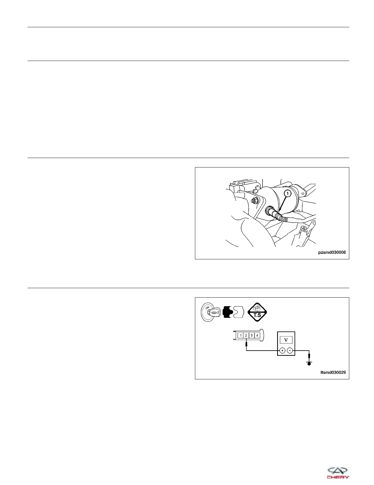
2.
CHECK O
2
SENSOR ELECTRICAL CONNECTOR
• Disconnect the O
2
sensor (1) electrical connector
E-004.
• Inspect the electrical connector for damage.
Is the electrical connector OK?
Yes
>> Go to the next step.
No
>> Repair or replace the electrical connector
as necessary.
3.
CHECK O
2
SENSOR HEATER POWER SUPPLY CIRCUIT
• Turn ignition switch on.
• Check the voltage between terminal 2 and ground
in the O
2
sensor connector E-004 terminal side.
• Battery voltage should exist.
Is the check result normal?
Yes
>> Go to Step 5.
No
>> Go to the next step.
DIAGNOSIS & TESTING
PZSMD030008
LTSMD030029
03–44
Chery Automobile Co., Ltd.
 Loading...


