2.
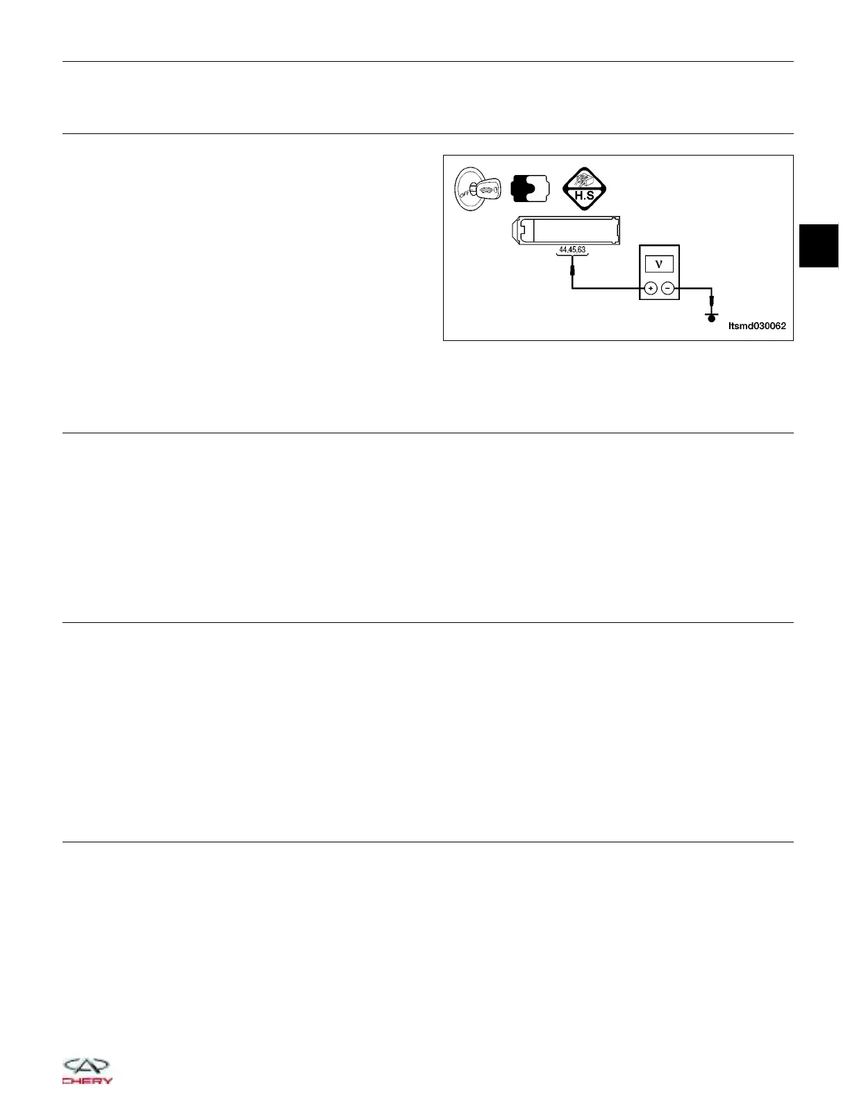
CHECK ECM POWER SUPPLY
• Check ECM supply between terminal 44, 45 or 63
and ground in the ECM electrical connector E-601,
terminal side.
Is the voltage between 9 - 17 V?
Yes
>> Replace the ECM.
NOTE : The Immobilizer control module
must be matched to the new ECM
(See ECM Removal & Installation
in Section 03 Electronic Engine
Controls).
No
>>
If the voltage is less than 9 V, go to step 3.
If the voltage is more than 17 V, go to step 6.
3.
CHECK SYSTEM VOLTAGE
• Connect the ECM electrical connector.
• Start the engine, raise the speed over 1000 RPM.
• Measure the charging system voltage with a digital multimeter at the battery positive and negative terminals.
Is the voltage less than 9 V?
Yes
>> Check the charging system.
No
>> Go to the next step.
4.
CHECK THE BATTERY
• Raise the speed over 1000 RPM for a few minutes.
• Turn ignition switch off.
• Measure the voltage drop with a digital multimeter at the battery positive and negative terminals while cranking
the engine.
• Battery voltage should be more than approximate 9 V.
Is the check result normal?
Yes
>> Go to the next step.
No
>> Charge or replace the battery.
5.
CHECK ECM POWER SUPPLY CIRCUIT
• Measure the resistance between ECM terminal 44, 45 or 63 and battery positive terminal.
• Continuity should exist.
Is the check result normal?
Yes
>> Go to the next step.
No
>>
Check fuse.
Inspect the harness.
Check all related components.
DIAGNOSIS & TESTING
LTSMD030062
03
03–145
Chery Automobile Co., Ltd.