Diagnostic Procedure
1.
CHECK GROUND CONNECTIONS
• Turn ignition switch off.
• Loosen and retighten ground screws on the body (See Ground Inspection in Section 03 Electronic Engine Con-
trols).
• Inspect ground connections E-801 and E-802 mounting positions (See Vehicle Wiring Harness Layout - ECM
Control Harness in Section 16 Wiring).
Are the ground connections OK?
Yes
>> Go to the next step.
No
>> Repair or replace ground harness or connections.
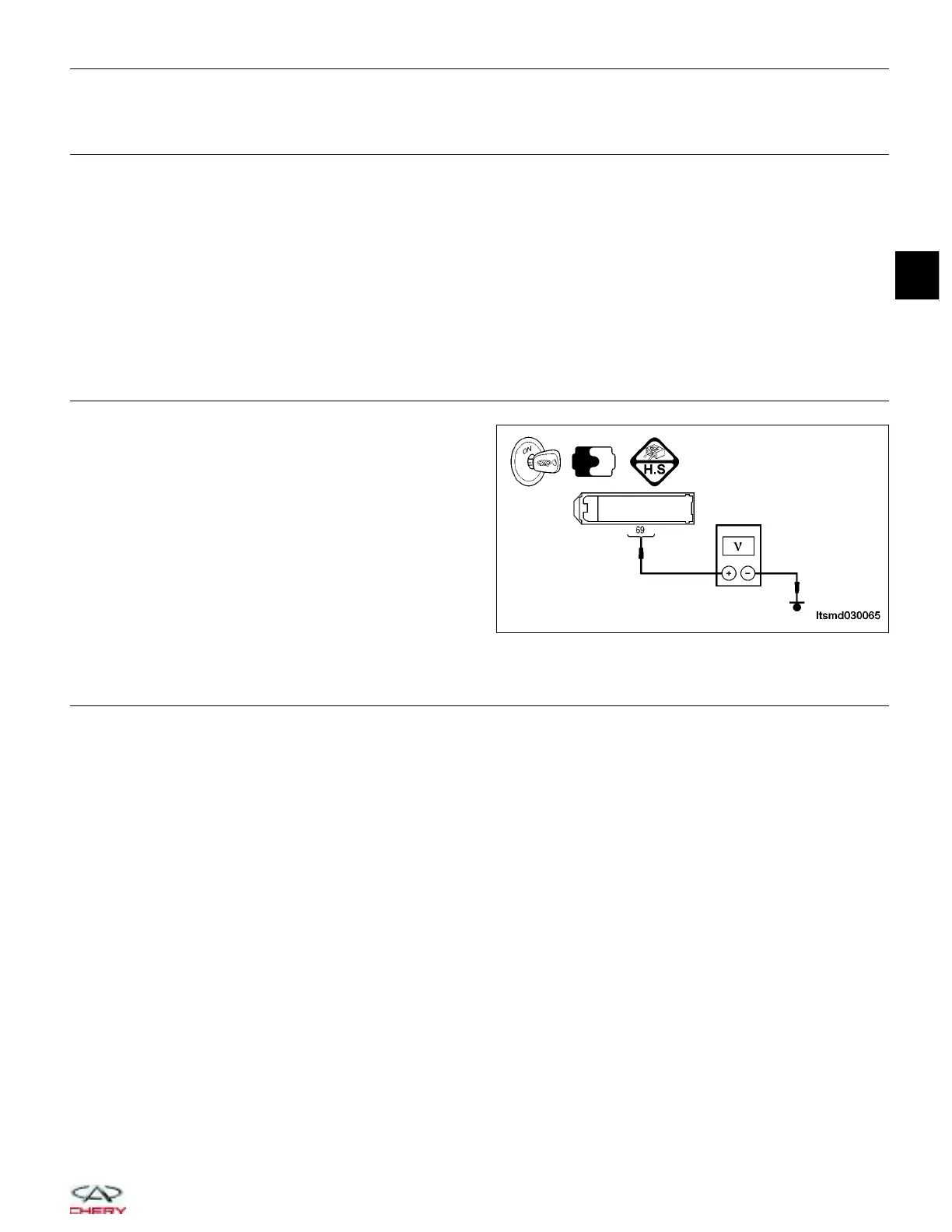
2.
CHECK A/C COMPRESSOR RELAY CONTROL CIRCUIT POWER SUPPLY CIRCUIT FOR OPEN
• Turn ignition switch on.
• Turn A/C switch off.
• Check A/C compressor relay control circuit between
ECM terminal 69 and ground in the ECM electrical
connector E-601, harness side.
• 12 V should exist.
Is the check result normal?
Yes
>> Go to step 4.
No
>> Go to the next step.
3.
DETECT MALFUNCTIONING PART
• Check the following for a possible malfunction:
− Fuse EF5
− Body fuse and relay box A-040
− A/C compressor relay, main relay
− Harness for an open or short between ECM terminal 14 and fuse EF5
− Harness for an open or short between ECM terminal 69 and fuse EF5
Is the check result normal?
Yes
>> Go to the next step.
No
>> Repair or replace malfunctioning part(s).
DIAGNOSIS & TESTING
LTSMD030065
03
03–153
Chery Automobile Co., Ltd.