Is the check result normal?
Yes
>> Go to the next step.
No
>> Repair circuit for short to ground or short to power in harness or connectors.
8.
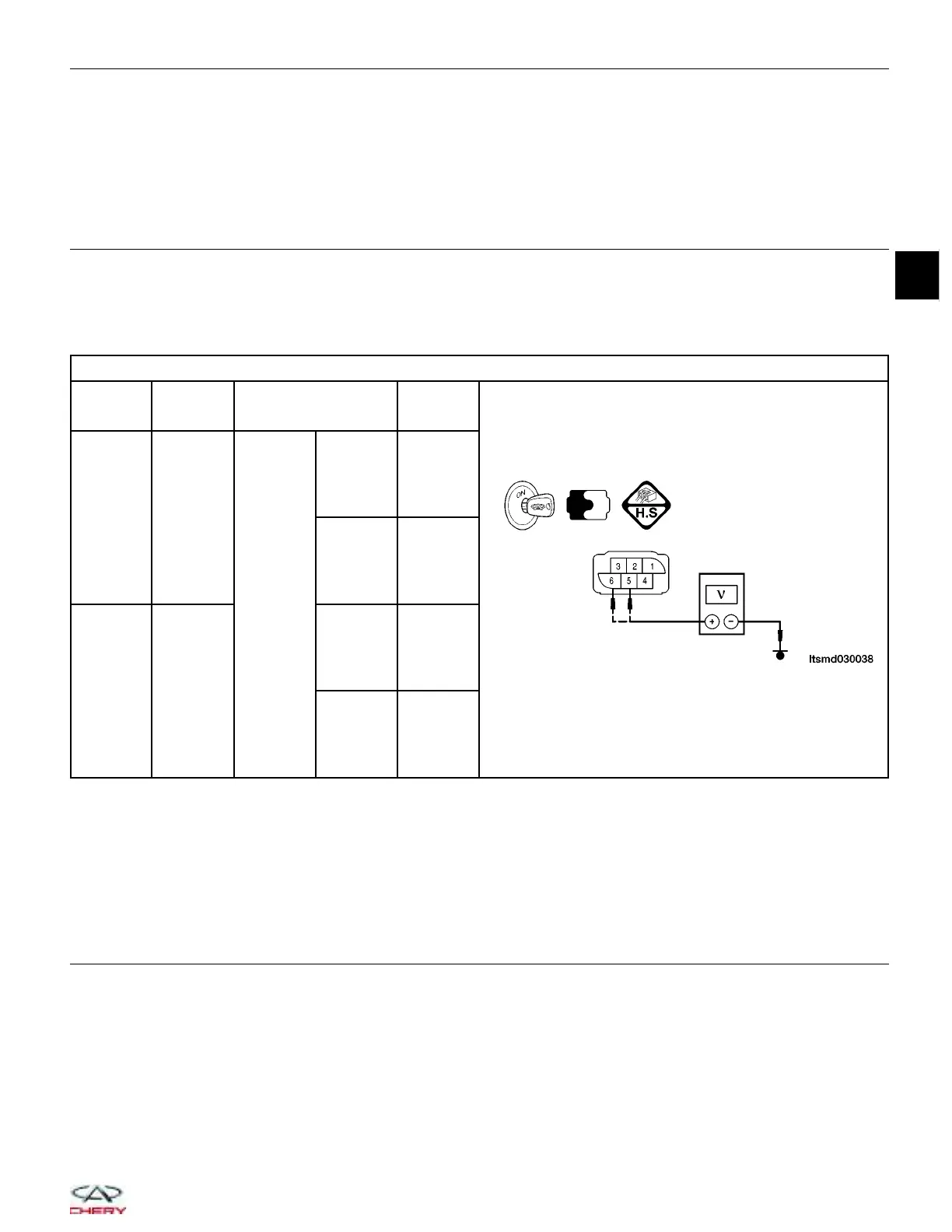
CHECK THE TPS
• Connect all harness connectors that have been disconnected.
• Turn ignition switch on.
• Check the voltage between ECM terminals 54 (TP sensor 1 (TPS1) signal), and 38 (TP sensor 2 (TPS2) sig-
nal) and ground under the following conditions:
TPS REFERENCE DATA
TPS
TERMINAL
NO.
ITEM CONDITION
VOLT (DC
VOLTAGE)
5
Electronic
throttle
control
actuator
(TPS2)
Ignition
switch: ON
Engine:
Stopped
Accelerator
pedal:
Fully
released
4.24 V
Engine:
Stopped
Accelerator
pedal:
Fully
depressed
0.72 V
6
Electronic
throttle
control
actuator
(TPS1)
Engine:
Stopped
Accelerator
pedal:
Fully
released
0.74 V
Engine:
Stopped
Accelerator
pedal:
Fully
depressed
4.62 V
Is the check result normal?
Yes
>> Go to the next step.
No
>>
Repair or replace the TPS circuits for a short or open.
If the TPS circuits are normal, replace the electronic throttle control actuator.
Perform throttle valve position self-learning.
9.
CHECK THE APPS GROUND CIRCUIT FOR AN OPEN OR SHORT
• Turn ignition switch off.
• Disconnect the ECM electrical connector.
• Check continuity between APPS2 terminal 2 and ECM terminal 35, and APPS1 terminal 5 and ECM terminal
36.
• Continuity should exist.
• Check harness for a short to power.
Is the check result normal?
Yes
>> Go to the next step.
No
>> Repair or replace the open circuit or short to power in harness or connectors.
DIAGNOSIS & TESTING
03
03–167
Chery Automobile Co., Ltd.
 Loading...