6. Installation is in the reverse order of removal.
Installation Notes:
• Using the special tool CH-20014 (1) tighten the six
clutch pressure plate retaining bolts (2).
Inspect
• Check the input shaft bearing to ensure it is able to rotate freely, replace the bearing if necessary.
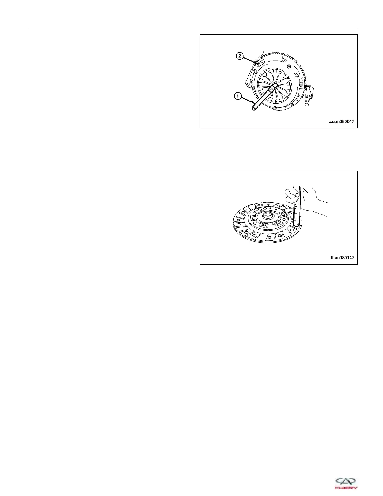
• Measure the depth of the recesses of the clutch friction lining rivet head, i.e., the distance between rivet head
and friction lining surface (as shown in the figure).
If the depth of any hole comes to the limit, replace
friction lining assembly .
(Standard: 1.2 mm)
(Limit: 0.5 mm)
• Check clutch pressure plate diaphragm spring for irregular wear or damage.
• Check clutch pressure plate for wear or hot spots.
• If found abnormal, replace the clutch plate assembly. Never separate the clutch plate assembly into the dia-
phragm spring and clutch plate.
• Check the contact surface of the flywheel and friction lining for irregular wear or hot spots. Repair or replace if
necessary.
CLUTCH ASSEMBLY SERVICE
PZSM080047
LTSM080147
08–46
Chery Automobile Co., Ltd.