GENERAL INFORMATION
Description
This vehicle is equipped with an unequal length half shaft system consisting of short left and long right half shafts.
The half shafts consist of a fixed Constant Velocity (CV) joint at the outboard end connected by a solid shaft to a
plunging CV joint on the inboard end. The inner CV joint has a splined end and is attached to the transaxle and is
retained with a snap ring. The outer joint has a splined connection to the wheel hub and is retained with a lock nut.
For further information on the front axle assembly see Front Sub-Frame Assembly Description & Operation in Section
10 Suspension.
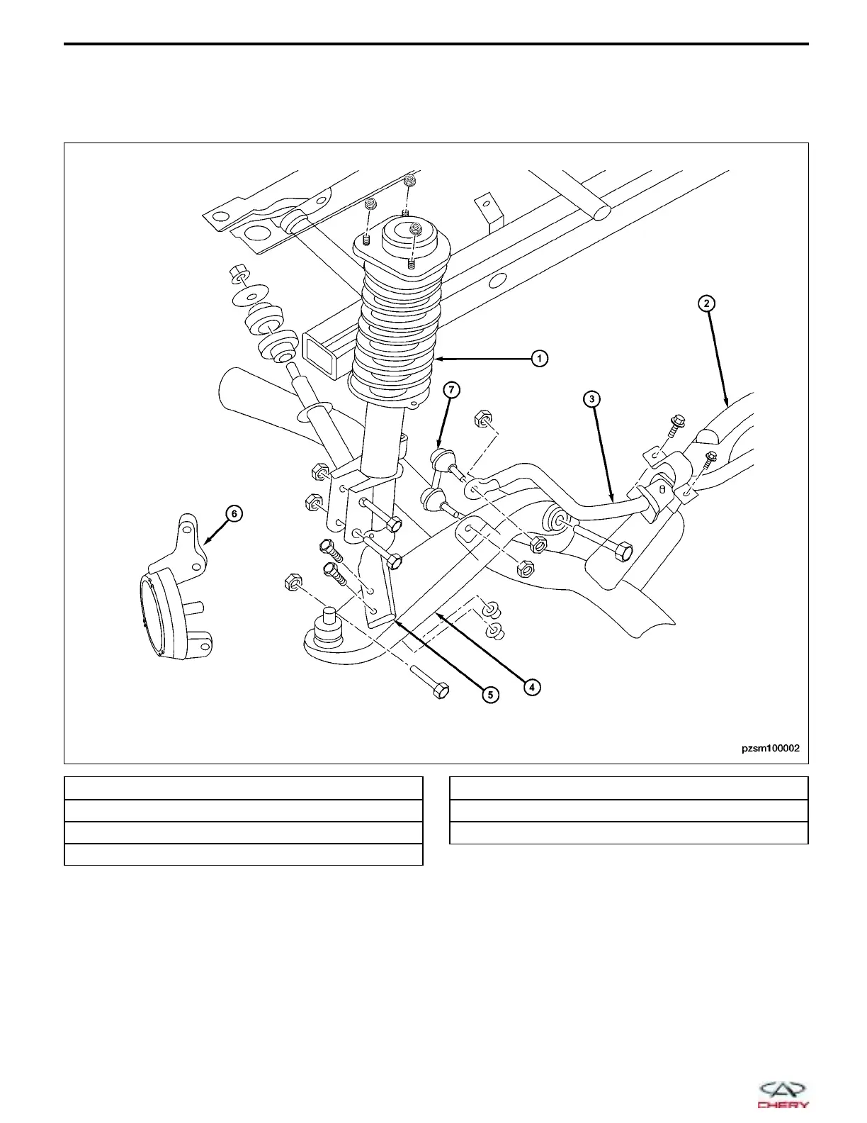
1 - Front Strut Assembly
2 - Front Sub-Frame
3 - Front Stabilizer Bar
4 - Front Lower Control Arm
5 - Front Strut Rod
6 - Front Steering Knuckle
7 - Front Stabilizer Bar Link
PZSM100002
09–2
Chery Automobile Co., Ltd.
 Loading...