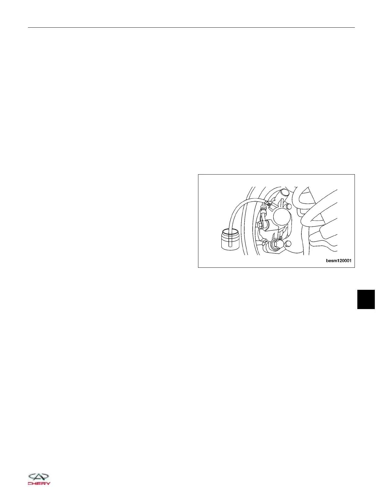
Attach a clear plastic hose to the bleeder screw and feed the hose into a clear jar containing enough fresh brake fluid
to submerge the end of the hose.
1. Turn the ignition switch off.
2. Have a helper pump the brake pedal three or four times and hold it in the down position.
3. With the pedal in the down position, open the bleeder screw at least one full turn.
4. Once the brake pedal has dropped, close the bleeder screw. After the bleeder screw is closed, release the
brake pedal.
5. Repeat the above steps until all trapped air is removed from that wheel circuit (usually four or five times).
6. Bleed the remaining wheel circuits in the same manner until all air is removed from the brake system. Monitor
the fluid level in the master cylinder reservoir to make sure it does not go dry.
7. Check and adjust brake fluid level to the 9MAX9 mark.
8. Check the brake pedal travel. If pedal travel is excessive or has not been improved, some air may still be
trapped in the system. Re-bleed the brakes as necessary.
9. Test drive the vehicle to verify the brakes are operating properly and pedal feel is correct.
Pressure Bleeding
NOTE :
Follow pressure bleeder manufacturer’s instructions for use of pressure bleeding equipment.
Attach the pressure bleeding equipment to the master
cylinder.
Attach a clear plastic hose to the bleeder screw and
feed the hose into a clear jar containing enough fresh
brake fluid to submerge the end of the hose.
1. Turn the ignition switch off.
2. Open the bleeder screw at least one full turn or more to obtain a steady stream of brake fluid.
3. After approximately 120-240 ml of fluid have been bled through the brake circuit and an air-free flow is main-
tained in the clear plastic hose and jar, close the bleeder screw.
4. Repeat this procedure at all the remaining bleeder screws.
5. Check and adjust brake fluid level to the 9MAX9 mark on the reservoir.
6. Check the brake pedal travel. If pedal travel is excessive or has not been improved, some air may still be
trapped in the system. Re-bleed the brakes as necessary.
7. Test drive the vehicle to verify the brakes are operating properly and pedal feel is correct.
Master Cylinder
Description
The master cylinder body is an anodized aluminum casting. It has a machined bore to accept the master cylinder
pistons and also has threaded ports with seats for hydraulic brake tube connections. The master cylinder has the
brake fluid reservoir mounted on top of it and supplies brake fluid to the master cylinder as required. The brake fluid
reservoir also feeds the clutch hydraulic circuit. The reservoir is made of clear plastic and it houses the brake fluid
level switch.
Operation
When the brake pedal is pressed, the master cylinder pistons apply brake pressure through the chassis brake tubes
to each brake assembly. The brake fluid reservoir supplies the brake hydraulic system with the necessary fluid to
operate properly.
ON-VEHICLE SERVICE
BESM120001
12
12–9
Chery Automobile Co., Ltd.
 Loading...