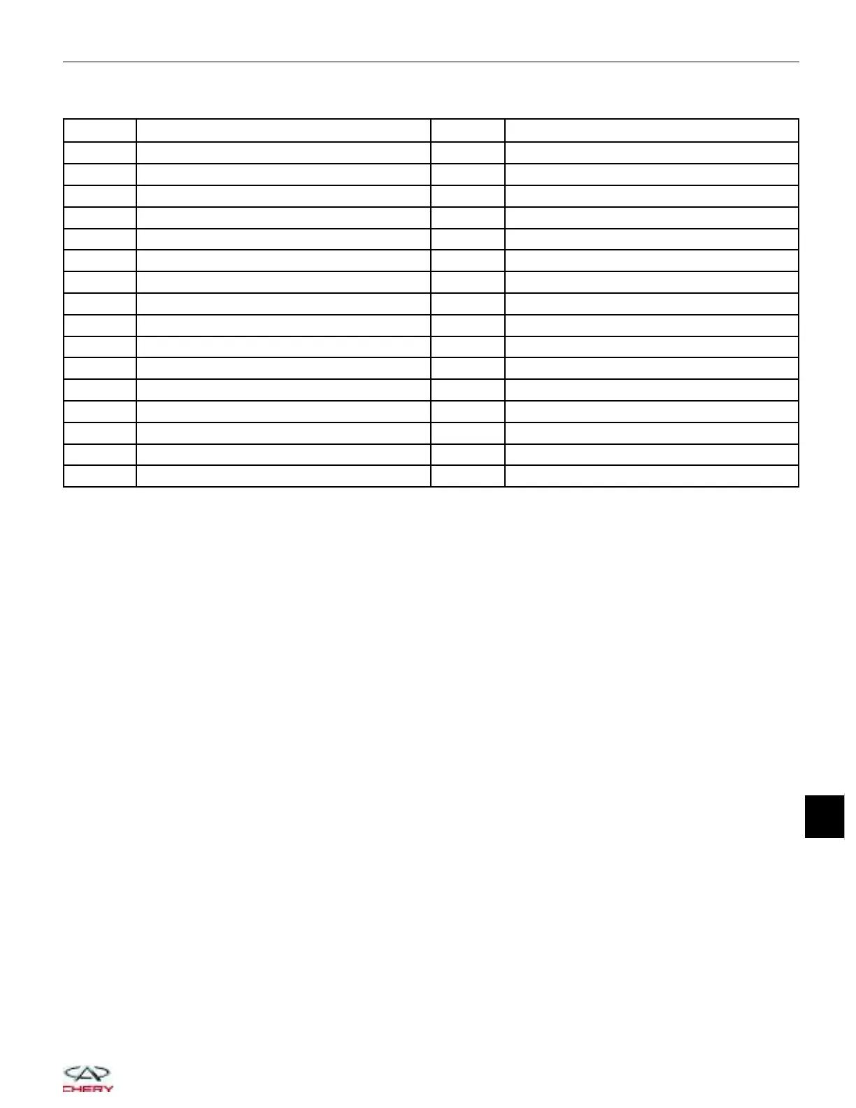
Instrument Cluster Module Connector Pin-Out Table
PIN CIRCUIT IDENTIFICATION PIN CIRCUIT IDENTIFICATION
1 - 17 -
2 Coolant Lever Sensor 18 Parking Brake Switch
3 GND (Power) 19 Seat Belt Buckle Switch LH
4 - 20 -
5 GND (Sensor) 21 Fuel Level Input
6 - 22 -
7 Speed Output 23 -
8 Reserve 24 -
9 Oil Pressure Switch 25 -
10 - 26 Brake Fluid Level Input
11 Continuous Supply Voltage 27 Vehicle Speed Input
12 Illumination Lamp 28 -
13 Ignition Switch 29 CAN-L
14 - 30 CAN-H
15 - 31 -
16 Charge 32 -
INSTRUMENT CLUSTER
15
15–85
Chery Automobile Co., Ltd.



 To Next Page