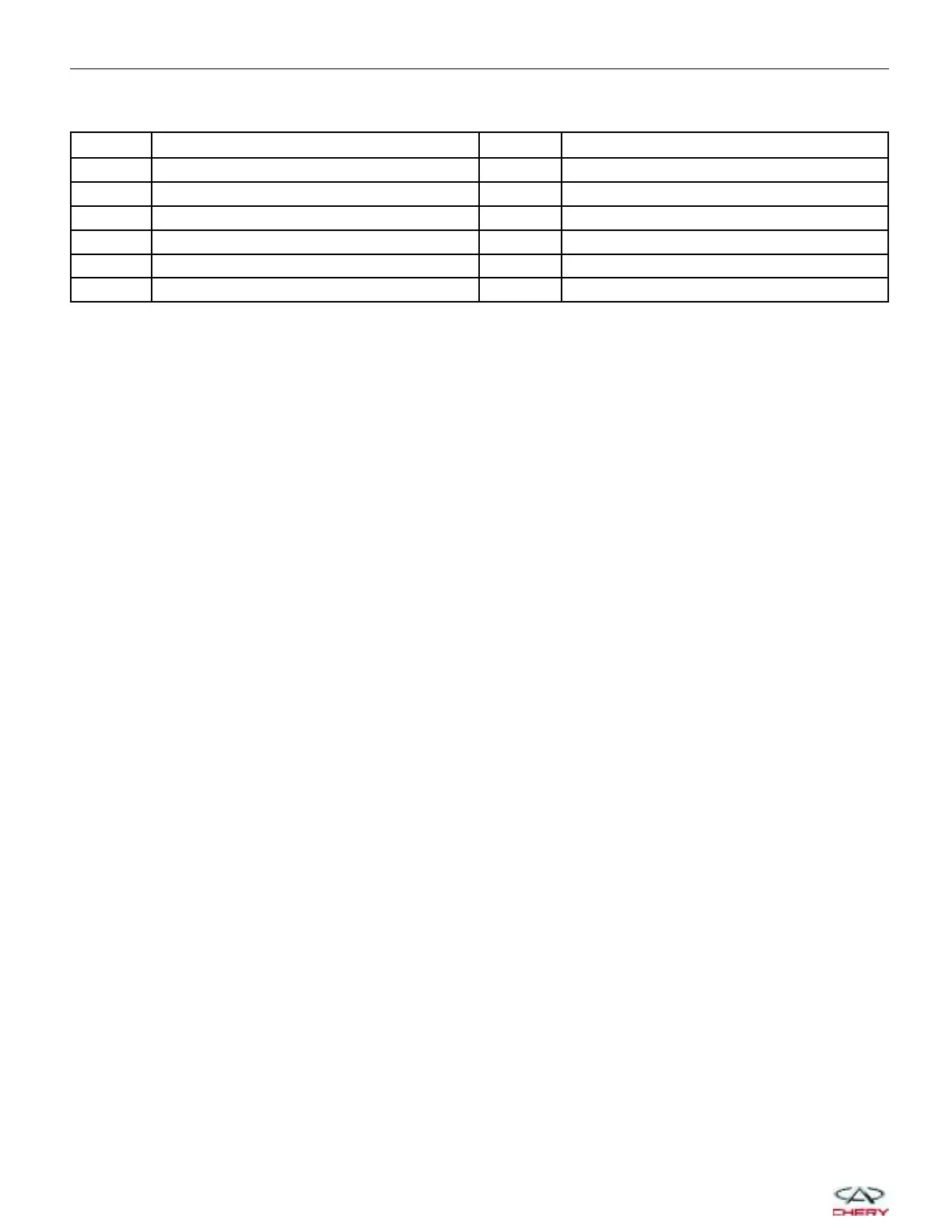
Immobilizer Control Module Connector Pin-Out Table
PIN CIRCUIT IDENTIFICATION PIN CIRCUIT IDENTIFICATION
1 Continuous Supply Voltage 7 Diagnostic Link K
2 GND 8 W-Line
3 — 9 Coil (GND)
4 Ignition Switch 10 Coil (ANT B)
5 R-Line 11 Coil (ANT A)
6 - — -
IMMOBILIZER CONTROL MODULE
15–120
Chery Automobile Co., Ltd.