3.
CHECK ENGINE CONTROL MODULE (ECM) ELECTRICAL CONNECTOR
• Turn ignition switch off.
• Disconnect the Engine Control Module (ECM) elec-
trical connector E-601 (1).
• Inspect the electrical connector for damage.
Is the electrical connector OK?
Yes
>> Go to the next step.
No
>> Repair or replace the electrical connector
as necessary.
4.
CHECK IMMOBILIZER CONTROL MODULE ELECTRICAL CONNECTOR
• Turn ignition switch off.
• Disconnect the Immobilizer control module electrical
connector C-025, C-026 (1).
• Inspect the electrical connector for damage.
Is the electrical connector OK?
Yes
>> Go to the next step.
No
>> Repair or replace the electrical connector
as necessary.
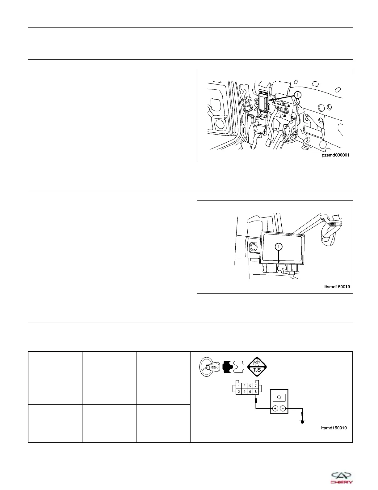
5.
CHECK IMMOBILIZER CONTROL MODULE AND ECM COMMUNICATION CIRCUIT
• For DTC B3042, check the resistance of W-Line between the Immobilizer control module connector C-025, ter-
minal 8 and ground.
IMMOBILIZER
CONTROL
MODULE
TERMINAL
TERMINAL RESULT
8 Ground
Continuity
should not exist
DIAGNOSIS & TESTING
PZSMD030001
LTSMD150019
15–130
Chery Automobile Co., Ltd.
 Loading...


