2.
CHECK IMMOBILIZER CONTROL MODULE DTC
• With the scan tool, view DTCs in the Immobilizer control module.
• Refer to DTC confirmation procedure.
Is DTC B3060, B3061 or B3077 present?
Yes
>>
For DTC B3060, go to step 6.
For DTC B3061, go to the next step.
For DTC B3077, go to step 7.
No
>>
The condition that caused the DTC is currently not present.
Monitor the scan tool data relative to this circuit while wiggle testing the wiring and connectors and
look for the DTC to reset.
− Using the electrical schematic as a guide, inspect the related wiring and connectors of the Immobilizer
control module.
− Verify that there is good terminal contact in the related connectors.
3.
CHECK IMMOBILIZER CONTROL MODULE ELECTRICAL CONNECTOR
• Turn ignition switch off.
• Disconnect the Immobilizer control module electrical
connector C-026 (1).
• Inspect the electrical connector for damage.
Is the electrical connector OK?
Yes
>> Go to the next step.
No
>> Repair or replace the electrical connector
as necessary.
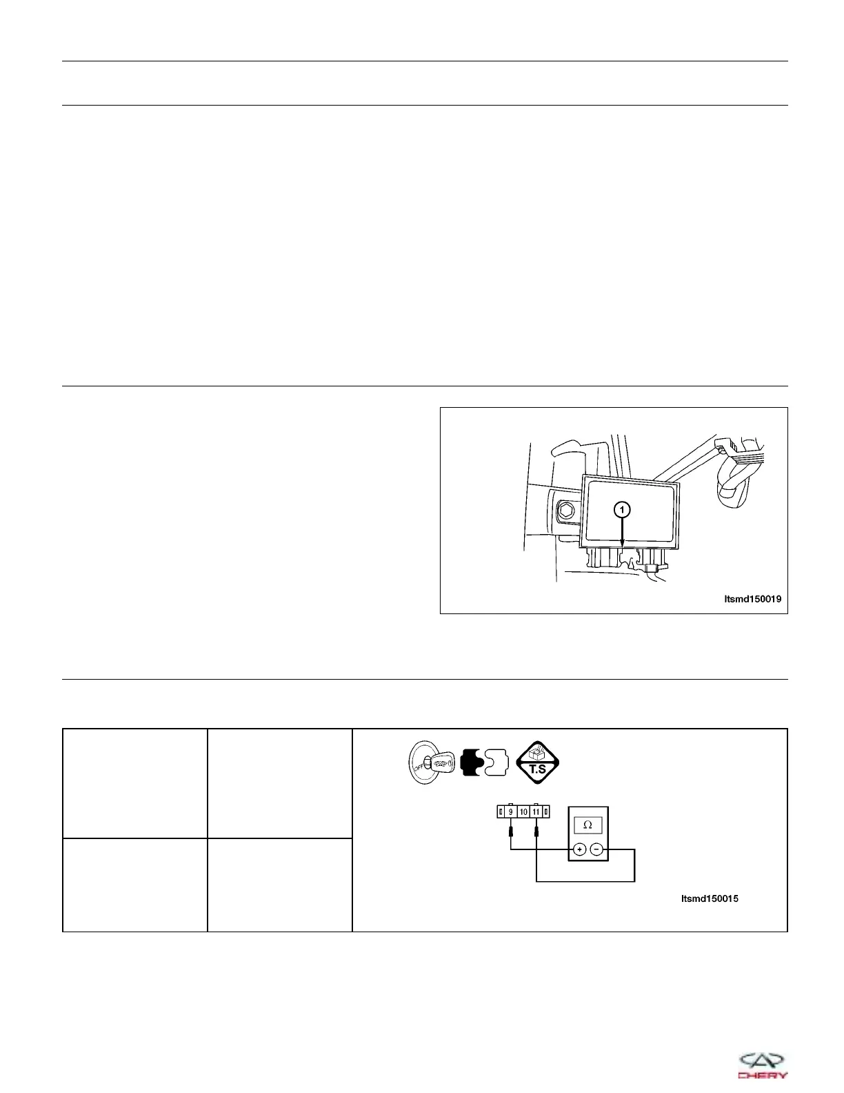
4.
CHECK THE IMMOBILIZER COIL
• Check the resistance between the Immobilizer coil connector C-026, terminal 9 and terminal 11.
IMMOBILIZER COIL
TERMINAL
IMMOBILIZER COIL
TERMINAL
9 11
Does the resistance range from 5 to 20 ohms?
Yes
>> Go to the next step.
No
>> Replace the Immobilizer coil.
DIAGNOSIS & TESTING
LTSMD150019
15–144
Chery Automobile Co., Ltd.
 Loading...


