The CS1070 1R output allows the Sink and AC signal currents to be set
directly. The CS1070 measures the rail voltage before applying current.
Make sure the CS1070 input power supply voltage is at least the rail voltage
+ 3V.
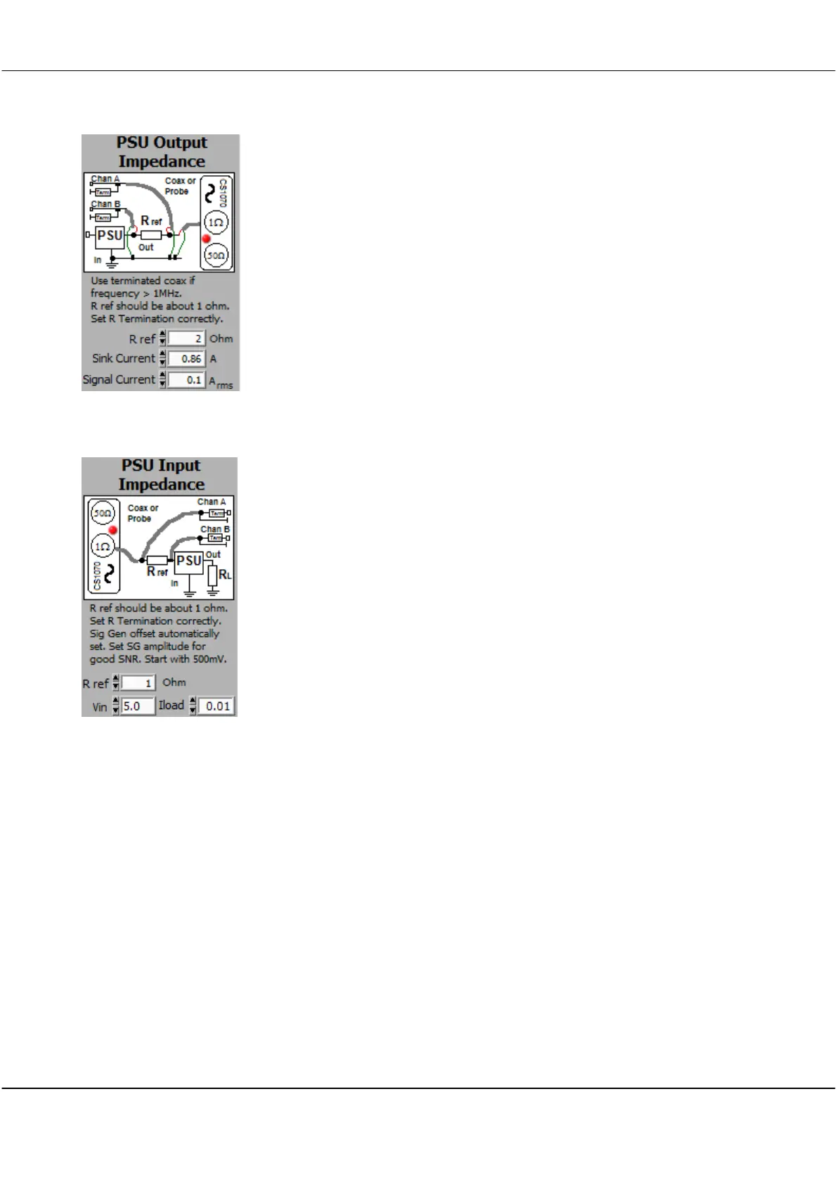
Optimum power transfer, performance and minimum EMC result when the
output impedance of the power supply is matched to the input impedance
of the load. Simply adding capacitance to the output of the power supply
may be counter-productive as it can lower the phase margin of the supply.
The optimum goal is that the impedance of the power plane matches the
impedance of the power supply, which matches the load impedance. Using
the FRA, you can measure the plane impedance, and then use capacitors
and/or inductors with appropriate ESR (or series resistors) to match the
power supply to the plane, and to the load.
The output impedance does determine the voltage rail ripple generated by
current demand at a particular frequency. It is Vr = Z Ir.
PSU Input Impedance - used to measure the Input Impedance of passive
or powered Power Supplies. You must use the CS1070 1R output. A
maximum of 1A is available. If you need more than 1A, we have an app
note on how to do this.
The phase is displayed. A phase of around 0 means a resistive load, -90 deg
is capacitive, +90 deg is inductive, and around -180 or +180 is a negative
impedance. Switch mode supplies exhibit negative impedance at low
frequencies because a positive change in input voltage results in a negative
change in current. As R = +V/-I, the resistance is negative.
PSU's are often preceded by an input filter to meet conducted EMC
requirements. A high Q filter has high impedance at the resonant frequency.
The filter can resonate with the negative PSU input impedance.
In addition, if the output impedance of the filter is higher than the closed
loop input impedance of the PSU, the total gain/phase response of the
Filter/PSU will be affected. This may include reducing the gain at the filter
resonant frequency, and modifying the phase, and therefore the transient
response of the combination, including forcing instability.
If the filter uses ceramic capacitors with very low ESR, the filter Q will be
high, increasing the possibility of oscillation. Electrolytic capacitors, with their
higher ESR, may be a better solution for the filter (but not the input to the
PSU, which demands low transient impedance). The ESR will damp the high
Q, and maintain the filter impedance. Alternatively a parallel connected
series R-C can be used to damp the filter at the resonant frequency. The R
serves to absorb the resonant current, while the C ensures the loss is not at
lower frequencies.
The FRA can be used to measure the output impedance of the filter (short
the input to do this) and the input impedance of the PSU without the filter.
You can make sure the filter Q is not high, and that the Filter output
impedance is always lower than the PSU input impedance.