Cleverscope CS300 Reference Manual v2.11
Page 174 www.cleverscope.com ©Cleverscope 2004-2015
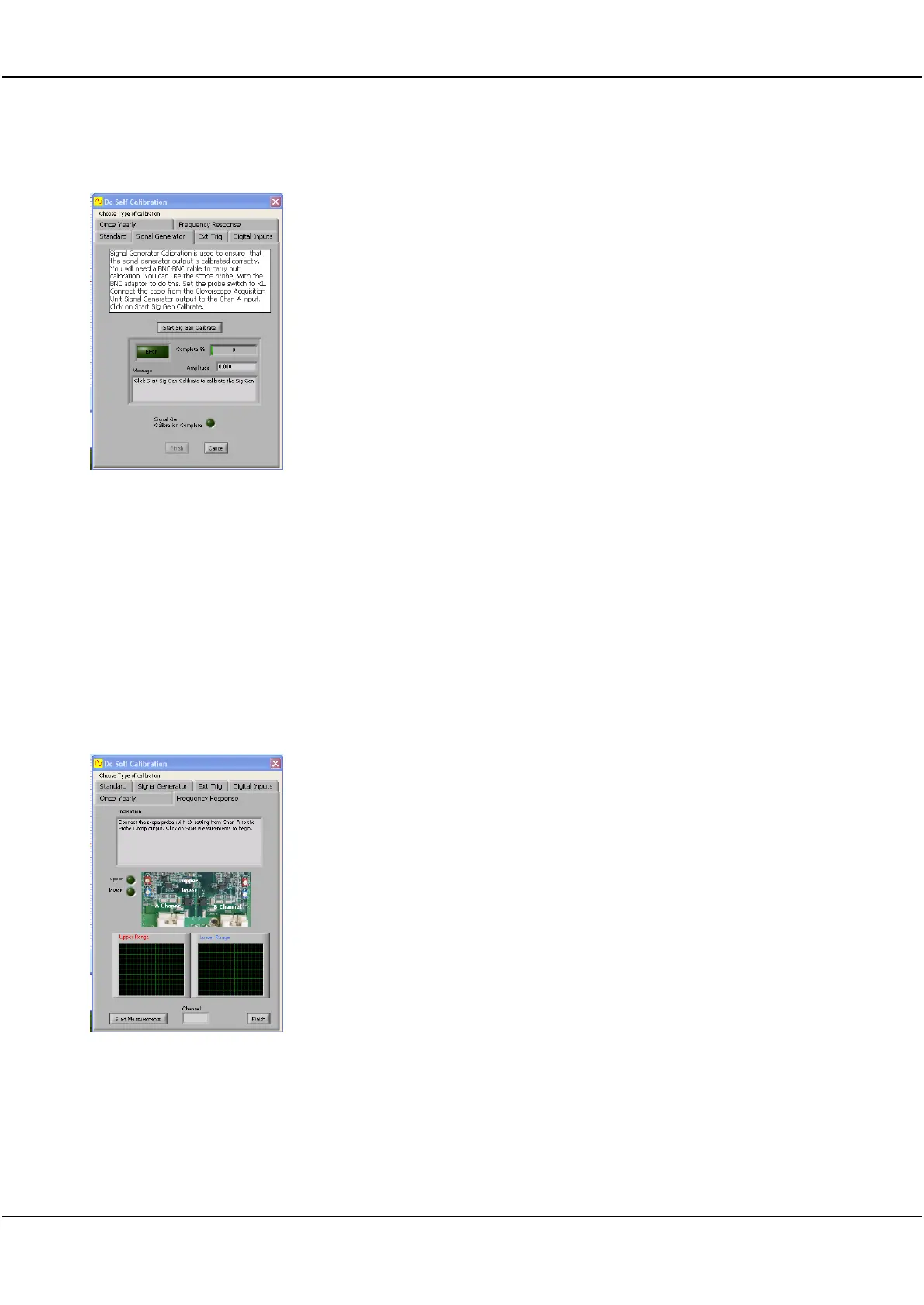
26.5 Digital Inputs Calibration
Click the one lead of a CS2004/5 probe set to Probe Comp
Connect a BNC-BNC cable from the Signal Generator to Channel A
Click Start Sig Gen Calibrate button
Wait until progress indicator reaches 100% and Sig Gen Calibration Complete
indicator glows Green and Finish button becomes active
Click Finish when completed
26.6 Frequency Response Calibration
Frequency Response is calibrated during assembly and the trim capacitors are sealed at the factory and seldom
require adjustment.
Important: If there is significant overshoot you will need to open the unit and remove the sealing glue to be able
to adjust the trim capacitors to get a square wave without overshoot.
With the power OFF use a Philips screwdriver to undo the two screws on the bottom of the Cleverscope case
assembly. Remove the lid, and power up with the lid still off. Leave it powered for 30 minutes to stabilise
operating temperature.
Frequency Response
Calibration
Click the Frequency Response tab.
Connect a BNC-BNC cable from the Signal Generator to Channel A.
Click Start Measurements button.
Switch Channel to Repeat for Channel B
Click Finish when completed.
Power off and replace the lid taking care not to over-tighten the case screws.