Cleverscope CS300 Reference Manual v2.11
Page 98 www.cleverscope.com ©Cleverscope 2004-2015
17.3 Use of the FRA with Power Supplies
One of the most important uses of the FRA is for measuring the gain/phase response of a Power Supply. The
response is used to establish stability and bandwidth.
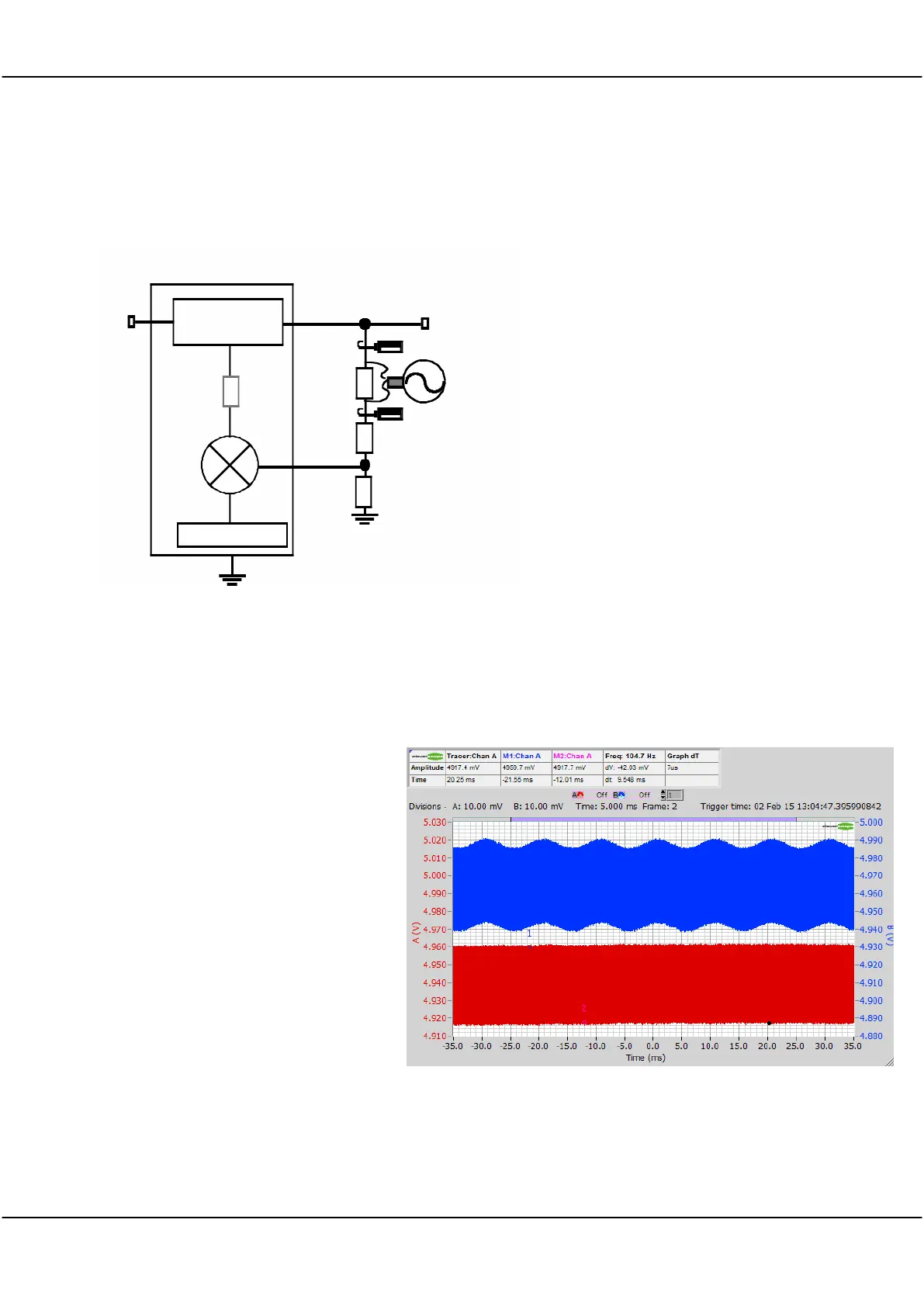
A generic power supply has this form:
The FRA injects a signal into the feedback
path that simulates perturbing V
out
. This
can be done either in the feedback chain,
as shown, or after the error amplifier (as
shown, greyed).
Key points are:
An isolated, low capacitance to ground
signal source is required. The isolated
CS701 is suitable. It is superior to
injection transformers as it has
performance to DC, and has much
lower ground capacitance and series
inductance, which act as parasitic
elements.
The injection point is characterised by a
low source impedance (and hence a
virtual AC earth) looking into a high
impedance destination. Vout is very
low impedance, while the feedback input is high impedance. This also applies to the error amplifier, and so
they are suitable injection points.
A small value series resistor (20 - 50 Ohm) is used to inject a signal which adds to the feedback signal. The
error amplifier sees this added signal and attempts to null it out.
The Signal Generator injected signal appears as a stimulus signal to the input of the feedback chain. This
stimulus is measured by Channel A.
The response signal is measured by Channel B, and is the output of the Power Modulator.
The signal frequency is swept over the
desired frequency range, while Channels
A and B measure the stimulus signals
synchronous with this frequency. The
measurement bandwidth is quite narrow
(between 0.1 Hz and 1KHz maximum)
which reduces the in-band switching
noise to achieve a useful signal to noise
ratio. This means the FRA can measure
the response to the signal frequency
independent of any other corrections the
error amplifier is making. Using this
method, we can measure the gain/phase
response of the Power Supply Unit. To
illustrate this here is a Switch mode
power supply exhibiting 50 mV of p-p
switch noise. Channel A is the stimulus
and Channel B the response (and output
of the power supply). In this example the Signal Generator was set to 10 mV p-p.