v2.13 Cleverscope CS300 Reference Manual
©Cleverscope 2004-2018 www.cleverscope.com Page 17
3.7 Compensate Probes
This is a good time to compensate your probes.
Go to the Cleverscope Control Panel window.
In the ACQUIRE area, set the Probe attenuation to
x10
.
In the TRIGGER area, set the trigger Level to
1
V.
You should be already viewing the Scope display.
If not the select the Scope display window from the Control Panel Window
menu.
Set the A channel graph axis to include the voltage range 0 to 4V.
Set the time axis to include the range –750 µs to + 750 µs.
Plug the scope probe into the A channel, attach the hook probe tip.
Set the probe switch (on the barrel of the probe) to x10.
Connect the ground crocodile clip to the right hand ground terminal.
Connect the probe to the left hand Probe Comp output terminal.
Go to the Cleverscope Control Panel window.
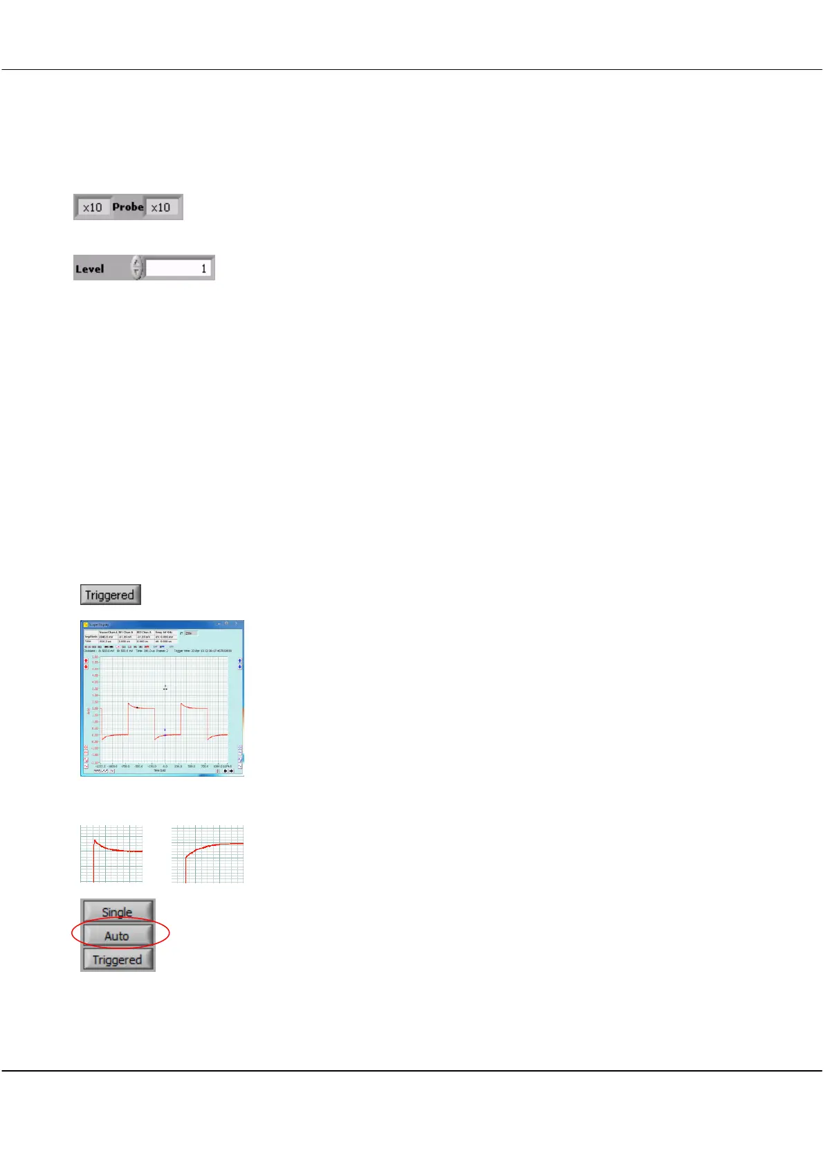
Click Triggered button and you should see a graph similar to that on the left.
<<<<
Overshoot or Slow Rise-time
Note The graph may have either over-shoot or slow rise-time.
Both overshoot and slow rise-time require correction to compensate the probe
capacitance and ensure a flat frequency response.
On the Control Panel click the Auto button.