Cleverscope CS300 Reference Manual v2.11
Page 150 www.cleverscope.com ©Cleverscope 2004-2015
21.9 SPI Protocol Example
Setting up the SPI protocol analyser
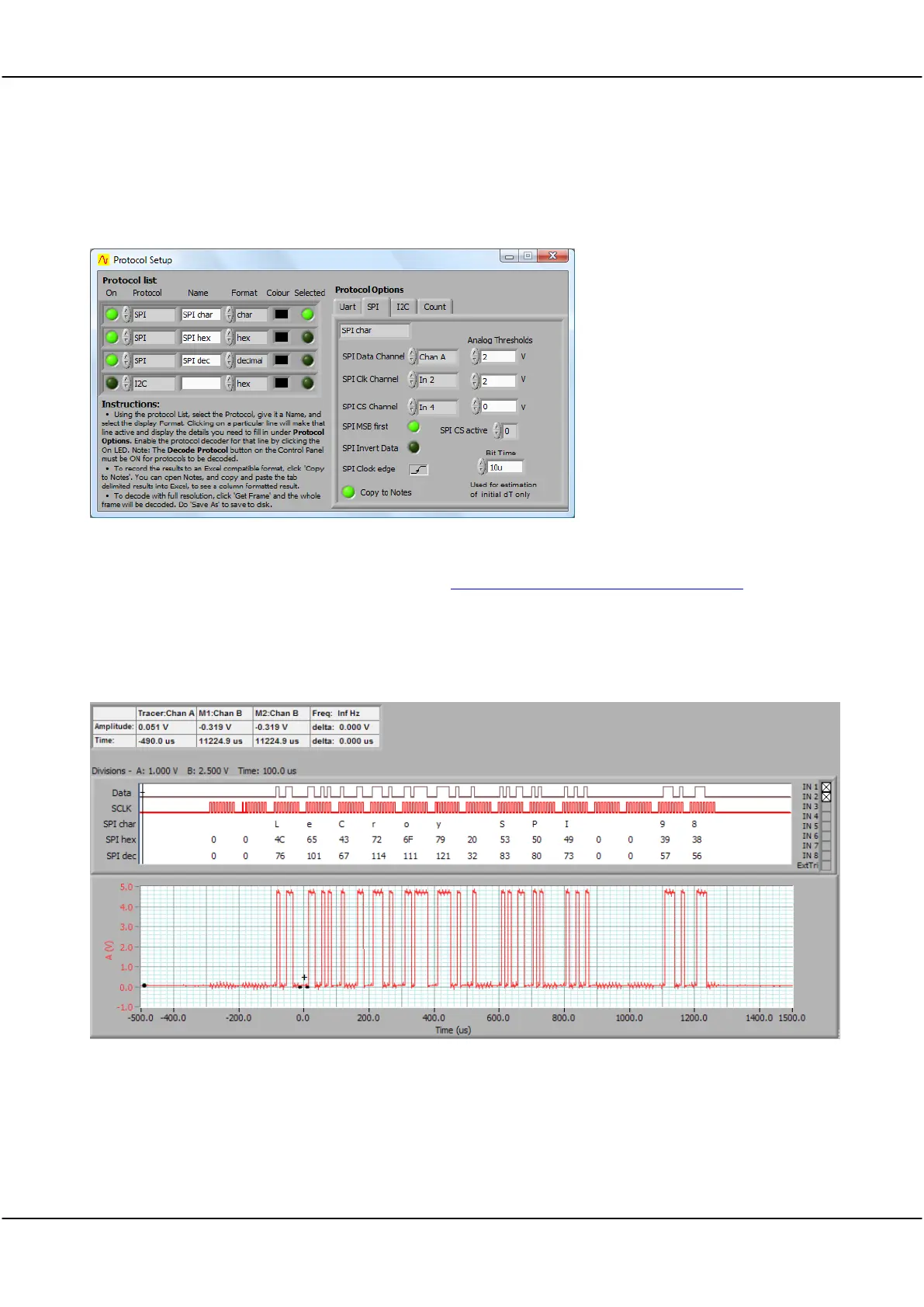
The protocol setup below shows Channel A used as the SPI Data Channel source:
Note: As an analog channel was used the signal threshold was at the given Analog Threshold (2V).
Watch a demonstration of SPI protocol decoding here www.youtube.com/watch?v=J5sZoDcagJM.
SPI protocol analyser output
The Scope display shows the colour coded SPI decode.
Note: The data line has been connected to both Input 1 and also Channel A.