Cleverscope CS300 Reference Manual v2.11
Page 32 www.cleverscope.com ©Cleverscope 2004-2015
4.7 Digital Pattern Triggering Zone [Control Panel]
The Digital Pattern is an optional qualifier to the analog trigger, or is used to define the digital trigger (Trigger
Source = Dig Trig). When used as a qualifier do NOT use digital edges, as it is extremely unlikely they will occur
at the same time as the analog edge.
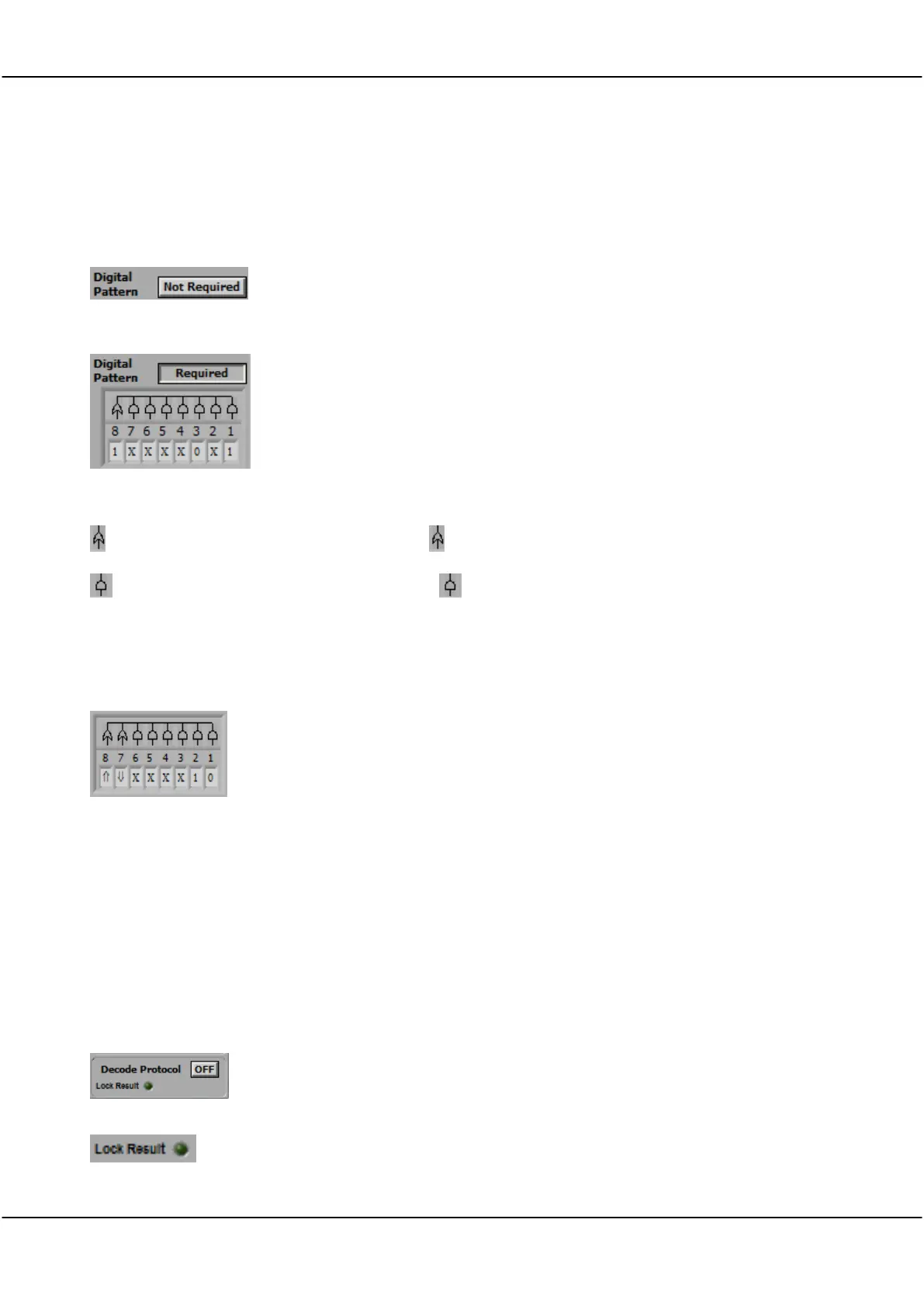
Digital Pattern Not Required
Digital Pattern Required
Click the button to toggle digital pattern triggering.
When Not Required is selected, analog triggering proceeds as explained
above. If the Trigger Source is Dig Trig, the button is ignored.
When Required is selected, the analog trigger cannot take place until the
digital inputs match the digital pattern chosen.
Example: If the Digital Pattern is set as per screen shot an analog trigger will
not be recognized until Digital Inputs 1 and 3 match 1 and 0 respectively, OR
Digital Input 8 is 1. Inputs labelled X are ‘don’t care’.
If the Trigger Source is Dig Trig, digital transitions are included to define the
trigger.
Click on the OR symbol above the digital input to set the OR option.
Click on the AND symbol above the digital input to set the AND option.
OR Triggering
AND Triggering
Triggering Conditions
Triggers when any one of the OR conditions are met.
Triggers when all of the AND conditions must be met.
0 – the digital input must be below the digital threshold
1 – the digital input must be above the digital threshold
X – the digital input is ignored
- the digital input transitions from 0 1
- the digital input transitions from 1 0
Note: When Digital Triggering is selected as the triggering Source then
Cleverscope will trigger when the digital inputs match the pattern set by the
digital input selection box.
Example: The pattern shown in the screen shot will cause a trigger if input 1 =
0, input 2 = 1, and either input 7 falls or input 8 rises.
4.8 Decode Protocol zone [Control Panel]
The protocol decoder is capable of decoding SPI, I
2
C, and RS232/422/485 serial data (UART).
Note: Decode Protocol is set up via the View menu Protocol Setup
Decode Protocol
Lock Result
Click button to toggle Off ON
Click button to toggle Lock Result ON or OFF.
With Lock Result set ON there will be no updates from the sampler.
Useful when using Maths to zoom in on the result on the Tracking Display without the
Maths being re-applied.