v2.13 Cleverscope CS300 Reference Manual
©Cleverscope 2004-2018 www.cleverscope.com Page 29
4.4 TRIGGER 1 Zone [Control Panel]
Trigger 1 is the main trigger and is setup in the TRIGGER area on the Cleverscope Control Panel.
Note: m=milliseconds, u=microseconds, n= nanoseconds
All the triggering controls are grouped in the TRIGGER zone apart from the trigger
cursors which are with the other tools at the top of the Cleverscope Control Panel.
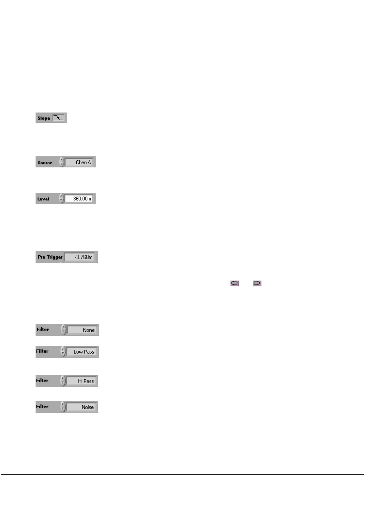
Click on the Slope symbol to toggle whether the voltage level will be increasing or
decreasing through the trigger point when triggering occurs.
The triggering slope is initially determined by the choice of an upward or downward
trigger cursor but it can be changed at any time using the slope button without
changing the level of the trigger point.
Click on the arrows or in the field to select the source of triggering.
Options are Channel A, Channel B, External trigger, Digital inputs, or the
Link input which is available on the Mini-Din connector at the back of the capture
unit.
Click on the arrows or type a value in the field to set the triggering Level
This is normally set using the trigger cursors in conjunction with the Scope Display.
A separate level is remembered for each source channel.
Note: Hysteresis is used to reduce false triggering due to noise. The normal hysteresis
is 2.5% of the amplitude range. Signals must fully transition through the hysteresis
band to cause a trigger.
The Pre Trigger time displayed is the time between the first sample in a frame and the
trigger point.
The trigger point is always set at time zero in the Scope Display.
The amount of pre-trigger time is determined by how much pre-trigger time you are
requesting to view in the Scope Display.
Scope Display left and right horizontal controls ( and ) set the pre-trigger time.
If the number is negative you are capturing signal before the trigger occurs. If the
number is positive you are waiting the given time following a trigger before capturing
the signal.
Click on the arrows or in the field to select a filter from the dropdown list.
Low Pass filtering is used to capture a low frequency signal in the presence of high
frequency noise.
Hi Pass filtering is used to capture high frequency signals (such as edges) in the
presence of a low frequency signal; for example triggering on a pulse on a mains
frequency waveform.
Noise filtering is used to achieve a more reliable trigger in the presence of large
amounts of noise. This is done by increasing the hysteresis band about the trigger
point to 7.5% of the amplitude range. A wider hysteresis band means that the signal
amplitude must be wider than the hysteresis band to ensure reliable triggering. Signals
must fully transition through the hysteresis band to cause a trigger.