Cleverscope CS300 Reference Manual v2.11
Page 58 www.cleverscope.com ©Cleverscope 2004-2015
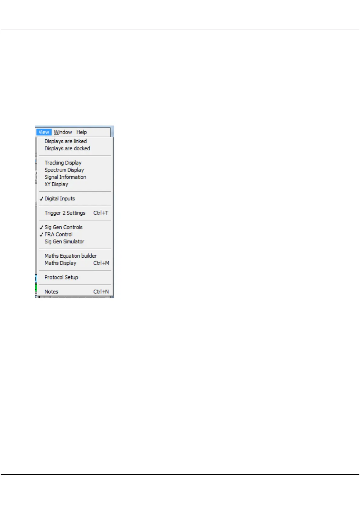
5.4 View Menu [Control Panel]
View menu allow you to set which displays are active.
Note: The Digital Inputs is not a separate window, but is built into the Scope Display or Tracking Display. The
Digital Inputs display can be de-selected to save screen space.
Note: the Scope display is always active although it can be resized or minimised but not closed.
Displays are linked
Tracking Display
Spectrum Display
Signal Information
XY Display
Digital Inputs
Trigger 2 Settings
Sig gen Controls
FRA Control
Sig Gen Simulator
Maths Equation Builder
Maths Display
Protocol Setup
Notes
Connects scope display signals to other displays.
used with the Scope Display for a close-up view.
displays the signal spectrum.
displays signal statistics.
displays an XY plot of Chan A against Chan B.
displays digital input lines and external trigger.
sets Trigger 2 parameters.
sets signal generator output (waveform, frequency,
level).
sets up test parameters for frequency response
measurement
provides controls for the virtual built-in signal
generator.
build equations to process signals.
display Maths Equation Builder results.
See section XXX Protocol Setup
Notes can be added to displays.
5.4.1 Displays are Linked
Click to link the tracer in the Scope Display to mimic the tracer in the Tracking
Display, and vice versa.
The menu option will show as ‘ticked’ when selected. There is no dialog for this
menu option.
Note The Tracking Display time axis will change to keep the tracer in the centre of
the graph.
Note If the Tracking Display is not linked, the two graphs can be manipulated
independently of each other.