Cleverscope CS300 Reference Manual v2.11
Page 90 www.cleverscope.com ©Cleverscope 2004-2015
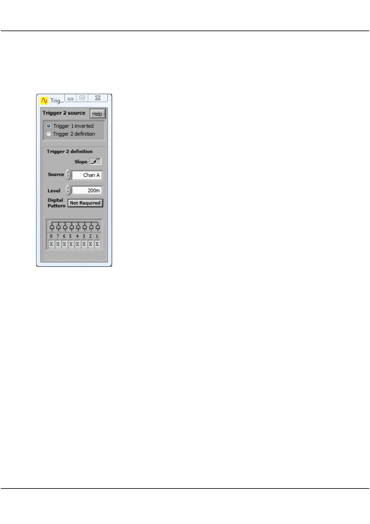
15 Trigger 2 Settings [View Menu]
Trigger 1
Inverted
Trigger 2
Definition
Click on the View menu at the top of the Cleverscope
Control Panel and select Trigger 2 Settings (or Ctrl + T).
Trigger 1 inverted sets Trigger 2 to trigger on the inverted
trigger of Trigger 1.
Defines Trigger 2 as per the Trigger 2 definition area below.
The Slope controls operate the same as the equivalent
controls for Trigger 1. The diagram below is displayed when
the Help button is clicked:
Selects whether the voltage level will be increasing or
decreasing through the trigger point when triggering
occurs. The triggering slope is initially determined by the
choice of an upward or downward trigger cursor but it can
be changed at any time using the slope button without
changing the level of the trigger point.
Click on the arrows or in the field to select the source of
triggering.
Options are: Channel A, Channel B, External trigger, or
Digital inputs.
Link input (Mini-Din connector at the back of the capture
unit).
Click on the arrows or type a value in the field to set the
triggering Level.
Trigger level is normally set using the trigger cursors in
conjunction with the Scope Display.
A separate level is remembered for each source channel.
Hysteresis is used to reduce false triggering due to noise.
The normal hysteresis is 2.5% of the amplitude range.
Signals must fully transition through the hysteresis band to
cause a trigger.
Click button to toggle whether a digital pattern is required
to qualify a trigger.