Cleverscope CS300 Reference Manual v2.11
Page 18 www.cleverscope.com ©Cleverscope 2004-2015
Adjust the small red screw in the body of the BNC connector end of the probe
until the graph is flat. Repeat the process for all oscilloscope probes.
Note You may like to do this on B channel, to familiarize yourself with the B
channel controls.
Reset Probe settings to x1 on Control Panel and probes
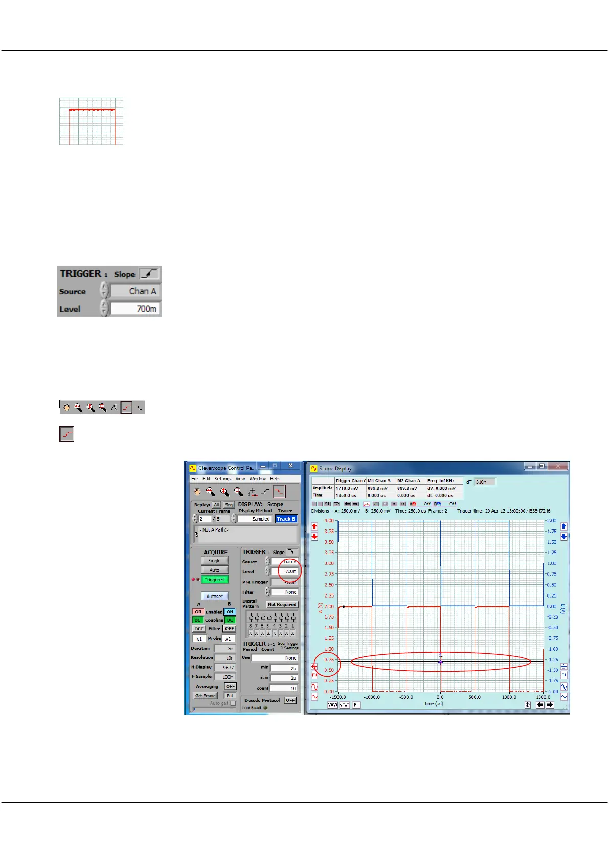
3.8 Changing the Trigger Edge
In the captures shown in the previous topics the Cleverscope has triggered on the falling edge. To change this
to trigger on the rising edge go to the TRIGGER area on the Control Panel.
Click in the Source field or use the arrows to select the trigger source.
In this instance it is to trigger from channel A (Chan A).
Click on the Slope symbol to toggle to a rising edge trigger.
3.9 Setting Trigger Level
On the Cleverscope Tools click on either the rising edge or falling edge trigger button.
In addition to setting the trigger to a rising or falling edge it should show a black line
across the display at the voltage level at which the display will attempt to trigger.
You should be able to see the display change to show a trigger on the selected edge.
You can toggle the trigger Edge button and watch the display in the Scope Display
change each time.