Cleverscope CS300 Reference Manual v2.11
Page 94 www.cleverscope.com ©Cleverscope 2004-2015
16.1 Using the CS700A Signal Generator Module
This example shows the internal signal generator module used to provide a signal to the Cleverscope Channel A
input. The incoming signal will be displayed on the Scope Display.
Note: If your Cleverscope was not supplied with a CS700A fitted then you can purchase the CS700A Signal
Generator hardware and install it in the Cleverscope Acquisition Unit by following the instructions that came
with it.
Pre-requisites
Internal Signal Generator module fitted and calibrated..
Probes compensated. (If not already compensated please follow instructions in the Cleverscope Basics and Probe
Compensation section.
Cleverscope connected to a PC.
16.2 Connect and Set Up
Connect one end of a BNC-BNC cable to SIG GEN at the rear of the Cleverscope.
Connect the other end of the cable to CHAN A at the front. The Sig Gen signal will be displayed on Channel A
of the Scope display.
Alternatively connect a probe to the Channel A input and then replace the probe tip with the BNC adapter and
plug the other end of the adapter into the signal generator BNC output on the rear of the unit.
Start the Cleverscope application software.
Click on the View menu on the Cleverscope Control Panel window.
Click Sig Gen Controls (if not already ticked).
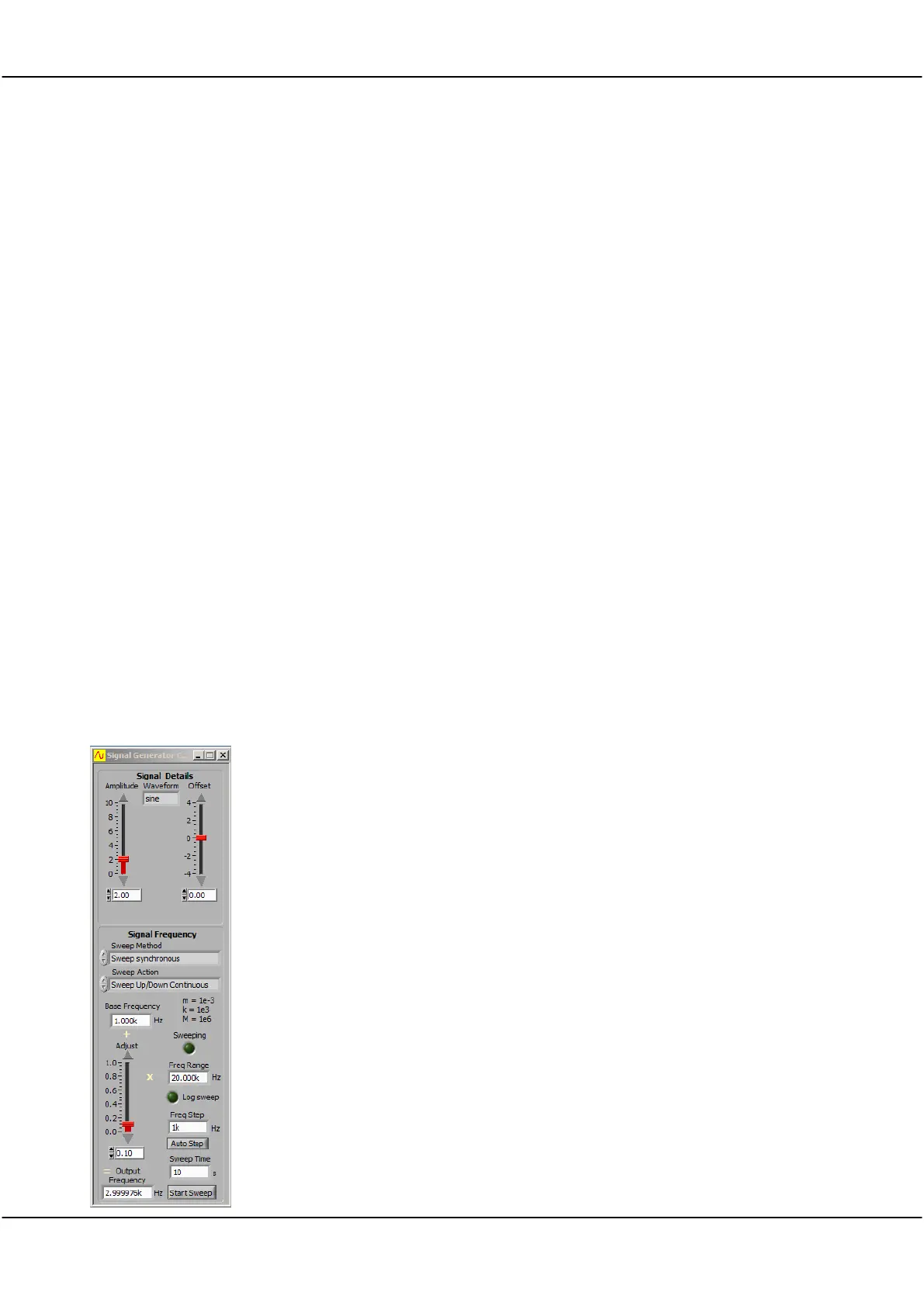
Set Signal Generator Controls
Set Waveform type to
sine.
Set Amplitude to
2
V.
Set Offset to
0
V, and
Set Sweep Method to
Single Freq
.
Set Base Frequency to
1k
Hz.
Set Freq Range to
20k
Hz.
Set Adjust to
0.1
.
Check Output Frequency is
3k
Hz (or very close to that value).