Cleverscope CS300 Reference Manual v2.11
Page 16 www.cleverscope.com ©Cleverscope 2004-2015
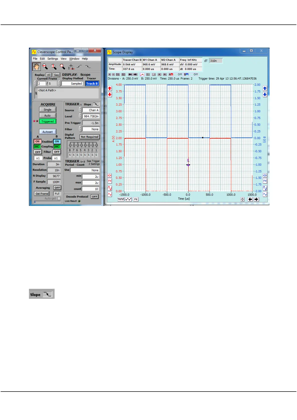
is displayed in the lower half of the Scope display and is coloured red.
The axis for channel A is on the left.
is displayed on the upper half of the Scope display and coloured blue.
Channel B axis is on the Right.
Note both channels are referenced to ground (0 volts) in their respective scales.
Both displays are shown on a common time axis with ‘0’ in the middle of the
graph.
Times to the left of ‘0.0’ are before rigger and time after ‘0.0’ post trigger.
The graph above shows the acquisition has triggered on the falling edge of
channel A at a trigger level of about 1V (984.7382m displayed in the Trigger 1
Level field).