v2.13 Cleverscope CS300 Reference Manual
©Cleverscope 2004-2018 www.cleverscope.com Page 99
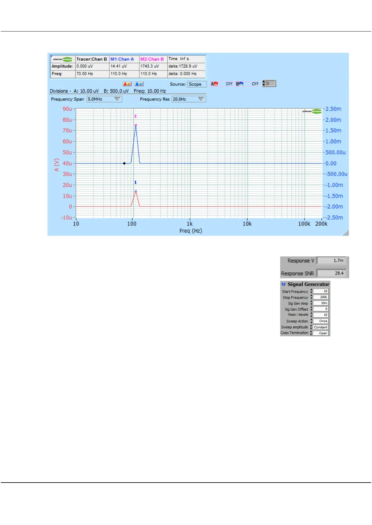
This results in the following Narrow Band Spectrum:
The stimulus (Chan A) has been reduced by the effects of the error amplifier to just 14.4 uV rms. The
response, which is the output of the power supply, has an amplitude of 1743 uV
rms. The gain of the loop is thus 1743/14.4 = 121 or 41.7 dB at 110 Hz. Both
signals are much smaller in amplitude than the p-p switching noise, and so cannot
be seen using a time-domain oscilloscope. Because the response amounts to only
1.7 mV rms, the power supply can be measured in operation without problems. The
Information panel displays the Response Amplitude as 1.7 mV rms, and the Signal to
Noise Ratio (SNR) as 29.4. The SNR is an important measure of signal quality. A
value >3 means that you can trust the results you are seeing. If the SNR is too small,
you should decrease bandwidth (20 Hz in this example), or increase the stimulus
(10mV p-p in this example).
Channels A and B are DC coupled so we can measure the response from DC up to
the maximum signal generator frequency of 65 MHz. They include the ability to DC offset to maintain
dynamic range. So you can for example measure a 100mV range centred on 24V DC.
Channels A and B have high dynamic range. An ADC is used which has sufficiently low differential non-
linearity to achieve 14 bits resolution. This is combined with dither to achieve more than 100 dB of dynamic
range (10uV in 1V FSD) when taking into account the FFT narrow band process gain.
The gain of the error amplifier serves to reduce the amplitude of the stimulus signal. An amplifier gain of 60
dB will reduce the stimulus signal 60 dB below the signal generator level. To counter-act this attenuation,
the signal generator amplitude can be programmatically varied in the range 1 mV p-p to 6V p-p (and 40V
p-p using the CS1070), a dynamic range of >70 dB. When using the 'Auto' or 'Table' method of sweep
amplitude control, we can vary the amplitude of the signal generator with frequency to counter the error
amplifier gain and maximize signal to noise ratio. This means we have a total dynamic range of about 170
dB available as a combination of signal resolution and signal generator amplitude.
Error amplifiers have gain that is high at low frequencies, and reduces as the frequency increases. The goal
of the power supply designer is to achieve a stable system with minimum ringing in response to a load step.
This is best achieved by having a positive phase margin, ideally in the range 50 - 60 degree as the system
gain goes through 0 dB (unity gain). As the phase margin reduces to 0 (and the phase lag through the
system is 180 degrees), the power supply output becomes more oscillatory. At 0 deg margin, the power
supply will oscillate continuously. Analysis of the circuit above shows that we can measure