Cleverscope CS300 Reference Manual v2.11
Page 100 www.cleverscope.com ©Cleverscope 2004-2015
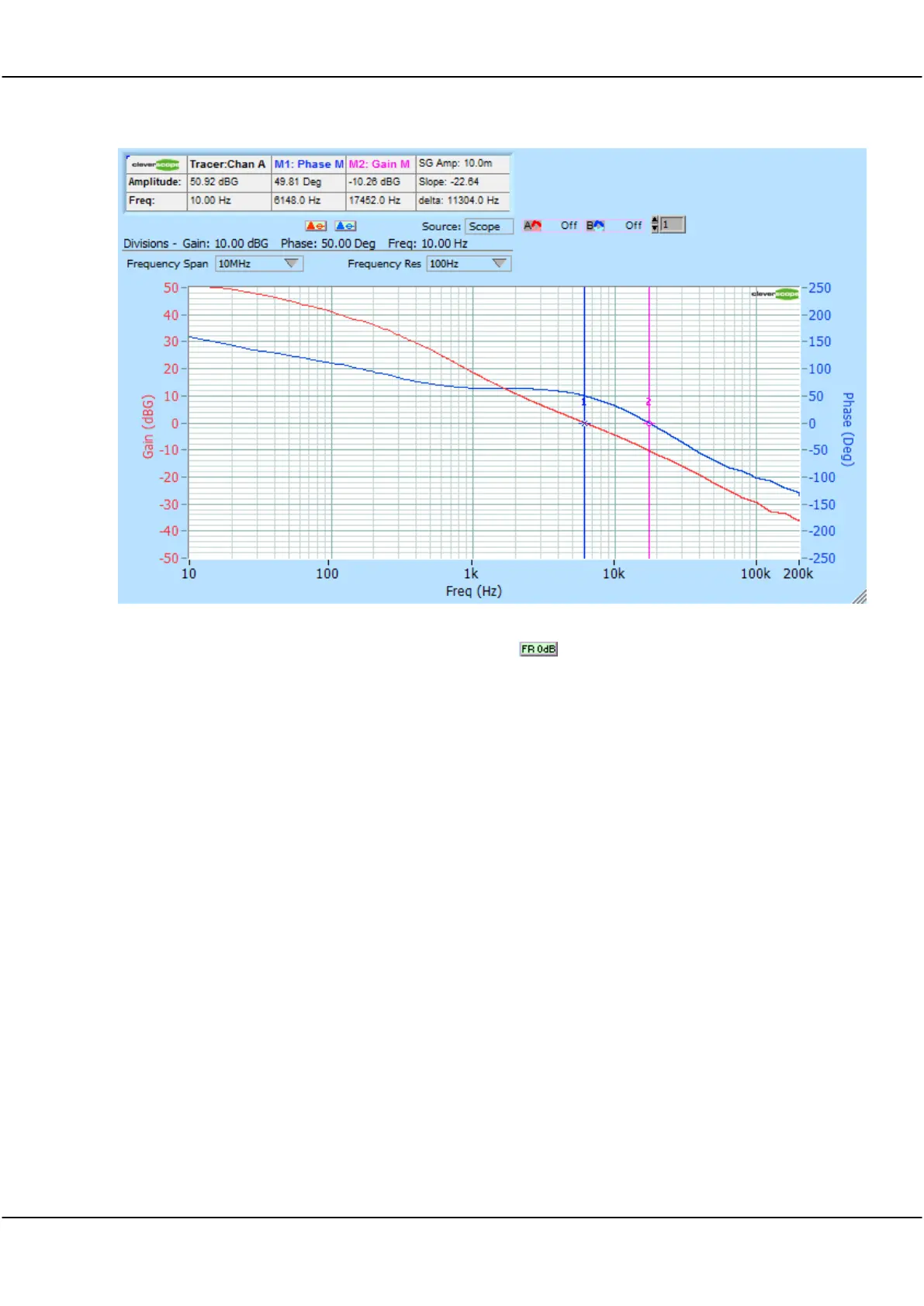
Response/Stimulus as a complex division to yield gain and phase. Here is an example response:
You can find the Gain and Phase margins by clicking on the button. This will automatically position
the vertical markers, and place the gain and phase margins, and the frequency at which they occur in the
Marker information area. In this example the Phase margin is 49.8 degrees at 6148 Hz where the gain
becomes unity. The Gain Margin of -10.2 dB where the phase margin becomes 0 is a measure of how
tolerant the design is to variation due to components, voltage, temperature and load.
This power supply has high gain (>50 dB) below about 20 Hz. It is here that we need a large signal
generator amplitude (the stimulus) to ensure a measureable response. The power supply output impedance
is proportional to gain. At high gains, the effective output impedance is low, and perturbations in load
current will not cause large changes in output voltage. As the frequency increases, gain reduces, and
effective output impedance increases. At some point, typically for a gain of less than 20 dB, the effective
output impedance becomes so high that the power supply does not source the load current without
significant output voltage variation. At this frequency we need an alternative current source - such as
output capacitors, to supply the load.
The gain/phase, or Bode plot, is useful to measure these factors:
Stability of the power supply (50 - 60 deg Phase Margin is ideal).
The susceptibility of the design to component, voltage or temperature change (Gain Margin). 10 dB is
minimum, 20 dB is good.
The frequency at which an alternate current source is required - 900 Hz in this case. This frequency allows
us to calculate the size of the output capacitors (from Z = 1/C), based on the desired output impedance.
We calculate based on the ripple voltage we allow. V
ripple
= Z I
load
, at the frequency of interest. For some
devices such as FPGA's which have a multitude of switching elements it is important to have low impedance
over a very wide frequency range (0 - 30 MHz is typical), while for audio amplifiers a much reduced range
of 0 - 20 kHz maybe all that is required. Choosing a higher bandwidth power supply unit will reduce the
cost and size of the output capacitors needed to maintain a low output impedance.