xStack® DES-3528/DES-3552 Series Layer 2 Stackable Fast Ethernet Managed Switch Web UI Reference Guide
VLAN Name VID Switch Ports
System (default) 1 5, 6, 7
Engineering 2 9, 10
Sales 5 1, 2, 3, 4
Port-based VLANs
Port-based VLANs limit traffic that flows into and out of switch ports. Thus, all devices connected to a port are
members of the VLAN(s) the port belongs to, whether there is a single computer directly connected to a switch, or an
entire department.
On port-based VLANs, NICs do not need to be able to identify 802.1Q tags in packet headers. NICs send and receive
normal Ethernet packets. If the packet’s destination lies on the same segment, communications take place using
normal Ethernet protocols. Even though this is always the case, when the destination for a packet lies on another
switch port, VLAN considerations come into play to decide if the packet gets dropped by the Switch or delivered.
VLAN Segmentation
Take for example a packet that is transmitted by a machine on Port 1 that is a member of VLAN 2. If the destination
lies on another port (found through a normal forwarding table lookup), the Switch then looks to see if the other port
(Port 10) is a member of VLAN 2 (and can therefore receive VLAN 2 packets). If Port 10 is not a member of VLAN 2,
then the packet will be dropped by the Switch and will not reach its destination. If Port 10 is a member of VLAN 2, the
packet will go through. This selective forwarding feature based on VLAN criteria is how VLANs segment networks. The
key point being that Port 1 will only transmit on VLAN 2.
802.1Q VLAN Settings
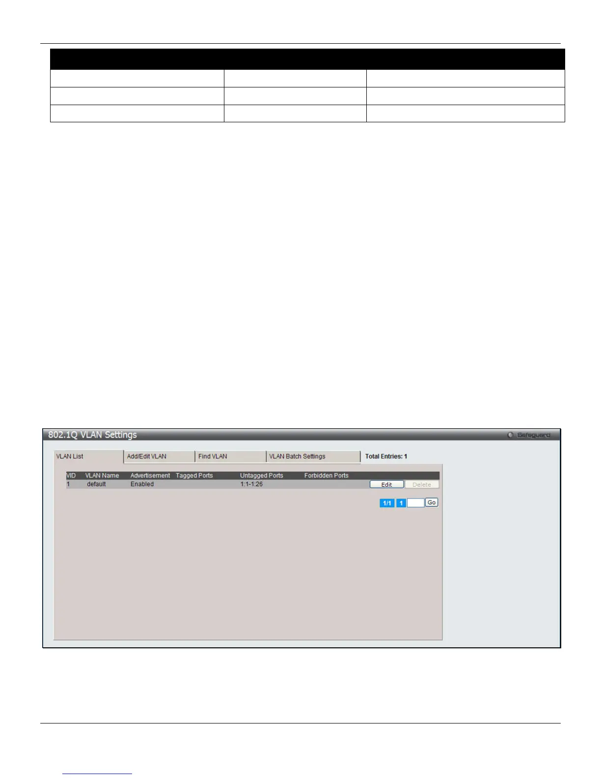
The VLAN List tab lists all previously configured VLANs by VLAN ID and VLAN Name.
To view the following window, click L2 Features > VLAN > 802.1Q VLAN Settings, as shown below:
Figure 4-4 802.1Q VLAN Settings –VLAN List Tab window
Click the Edit button to re-configure the specific entry.
Click the Delete button to remove the specific entry.
Enter a page number and click the Go button to navigate to a specific page when multiple pages exist.
61