User's Manual
19
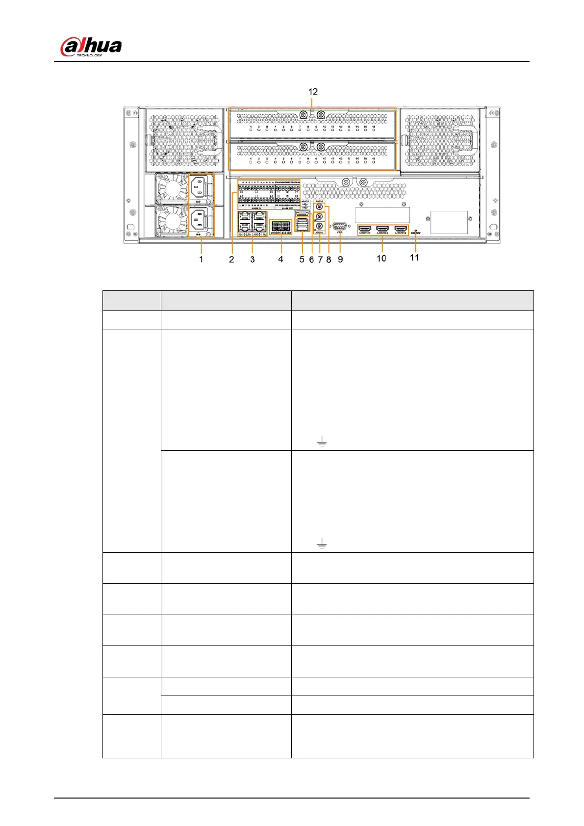
Figure 2-28 IVSS7024-M rear panel (redundant power)
Table 2-9 Rear panel description (1)
1 Power input port Inputs 100-240 VAC power.
2
Alarm Input
16 groups (1–16) alarm input ports. They are
corresponding to ALARM 1–ALARM 16. The alarm
becomes valid in low level.
●
A and B: Control the A/B cable of the RS–485
device. It is used to connect to the PTZ camera.
Please connect 120 Ω between A/B cables if
there are too many PTZ decoders.
●
: GND end.
Alarm Output
8 groups of alarm output ports (NO1 C1–NO8 C8).
They output alarm signal to the alarm device. Please
make sure there is power to the external alarm
device.
●
NO: Alarm output port of Normally Open type.
●
C: Common alarm output port.
●
: GND end.
3 Network port
10/100/1000Mbps self-adaptive Ethernet port.
Connects to the network cable.
4 SAS port
SAS extension port. It can connect to the SAS
extension controller.
5 USB port
Connects to external devices such as USB storage
device, keyboard and mouse.
6 eSATA port
SATA peripheral port. Connects to SATA port or
eSATA device.
7
AUDIO IN Audio input port
AUDIO OUT Audio output port
8 RS-232 port
RS-232 COM debug. It is used for general COM
debug, setting IP address, and transmitting
transparent COM data.
 Loading...